The AEB system is designed to help avoid or reduce the severity of a potential collision when drivers brake inadequately, brake late, or do not brake at all to avoid a collision.
The system detects road risk factors using the forward-facing sensor, warns the driver, and activates emergency braking to prevent a collision or reduce the impact speed.
The system control process is as follows.
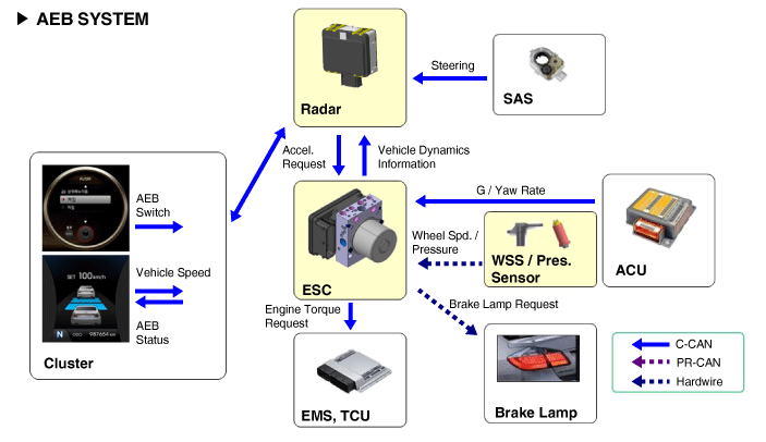
Confirm the AEB target object (vehicles and pedestrians) using the analyzed data.
Calculate the required deceleration based on speed, distance, and the presence or absence of a preceding vehicle.
Transmit the "Required Deceleration" to the Electronic Stability Control (ESC) System (CAN Communication)
After calculating the required torque to achieve the "Required Deceleration" (CAN message), the ESC performs automatic control.
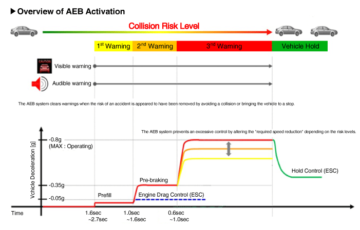
Operation
※ The indicated time will vary depending on vehicle speed.
Step 1: Issue a visual (display) and audible warning when a hazard is detected.
Step 2: Reduce engine torque and activate AEB when the probability of a collision is high.
Step 3: Activate emergency braking when a collision is unavoidable.
After the vehicle stops: Hold the brake pedal for a specified time, then release it.
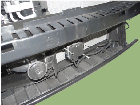
Components and Component Location
Components
The AEB system configuration is as follows.
Detection device (radar) that can recognize potential obstacles ahead.
Human Machine Interface (HMI) to warn the driver or change settings.
Brake system for automatic braking of the vehicle.
Circuit Diagrams
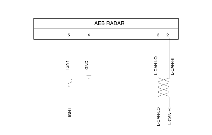
Schematic Diagram
Terminal Function
NO.
Terminal Function
1
-
2
C-CAN LOW
3
C-CAN HIGH
4
GROUND
5
IGN1
6
-
7
-
8
-
Repair Procedures
Inspection
The AEB ON/OFF switch can be set in the USM (User Setting Menu); the factory setting is ON. When the ignition is switched on, the system maintains the default ON state and does not reflect the driver's setting at the next ignition cycle. If the ESC function is turned off, the AEB function is also turned off.
AEB ON/OFF is set in USM (User Setting Mode) and is ON by default.
While IGN is ON, it remains ON; however, driver settings do not take effect the next time IGN is turned ON.
When ESC is OFF, AEB is also OFF.
Removal
Turn the ignition switch OFF and disconnect the negative (-) battery cable.
Remove the front bumper cover. (Refer to Body - "Front Bumper Assembly")
Loosen the bolts, then disconnect the AEB unit connector.
Installation
AEB Radar
Installation is the reverse of removal.
Perform AEB variant coding.
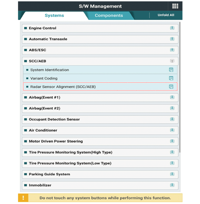
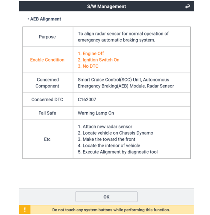
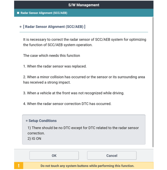
Perform AEB radar alignment.
Autonomous Emergency Braking (AEB) System Radar Sensor Alignment
The AEB system is designed to help avoid or reduce the severity of a potential collision when drivers brake inadequately, brake late, or do not brake at all to avoid a collision. For correct operation, the radar sensor must be properly aligned parallel to the vehicle's direction of travel. For this reason, the radar sensor alignment procedure must be performed whenever the sensor has been reinstalled or replaced. If the sensor alignment procedure is not performed under the conditions mentioned above, the smart cruise control system may not operate correctly.
Autonomous Emergency Braking (AEB) System Radar Sensor Alignment
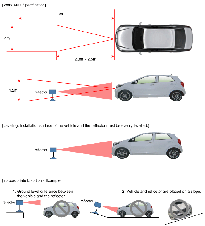
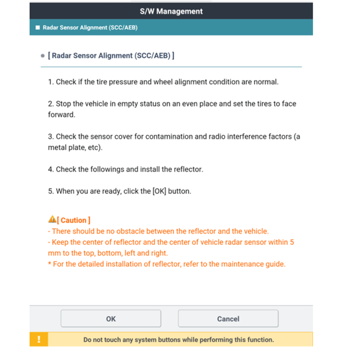
Park the vehicle on a level surface.
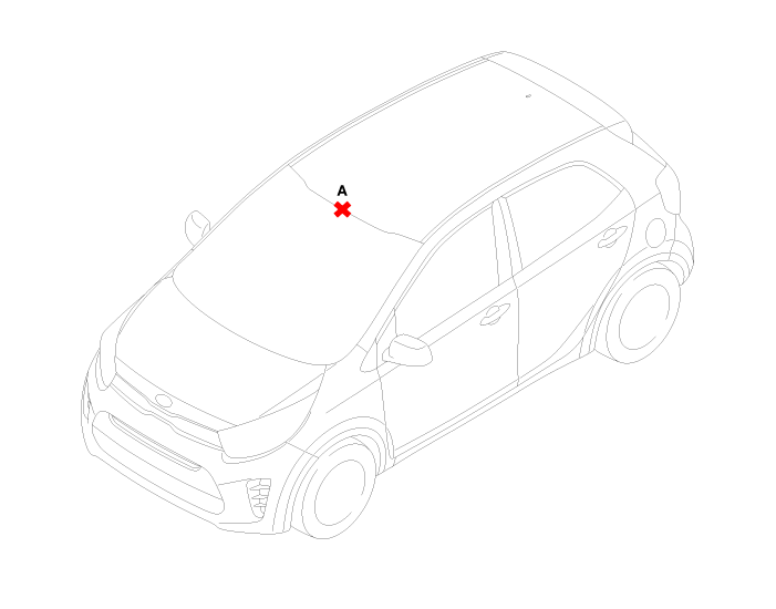
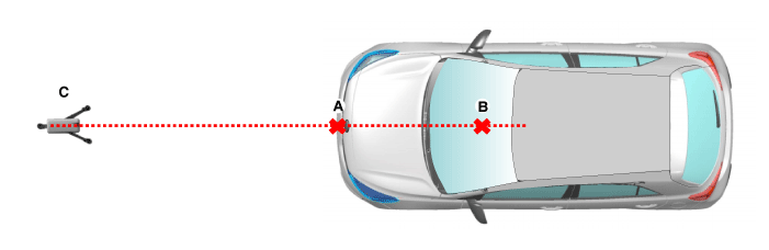
Mark the center point on the upper part of the windshield (A).
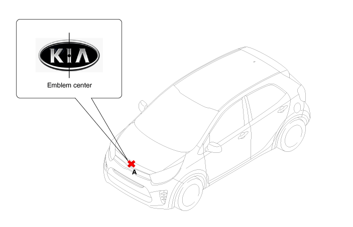
Mark the center point of the emblem (A).
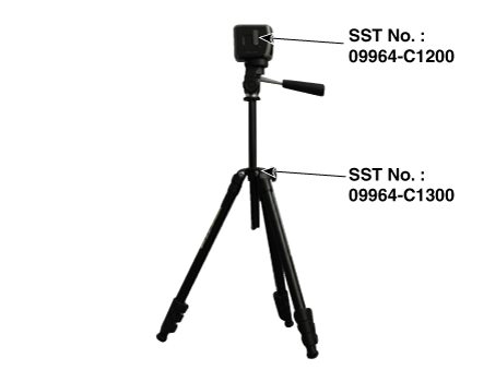
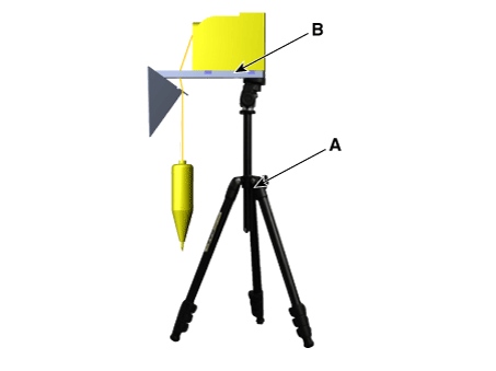
Install the SCC calibration laser [SST No.: 09964-C1200] on the tripod [SST No.: 09964-C1300].
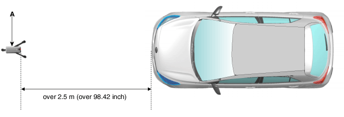
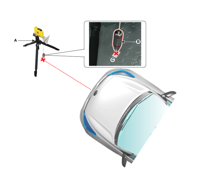
Install the vertical/horizontal laser [SST No.: 09964-C1200] (A) at a distance of at least 2.5 m from the front of the vehicle.
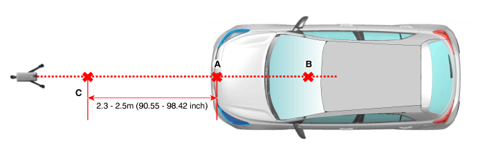
Align the vertical laser line with (A) and (B) using the vertical/horizontal laser (C) [SST No.: 09964-C1200].
Mark (C) at a distance of 2.3–2.5 m (90.55–98.42 in.) from (A) in front of the vehicle.
If possible, perform the calibration at a distance of 2.5 m.
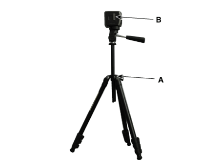
Remove the SCC calibration laser [SST No.: 09964-C1200] (B) from the tripod [SST No.: 09964-C1300] (A).
Install the reflector [SST No.: 09964-C1100] (B) on the tripod [SST No.: 09964-C1300] (A).
Align the vertical weight (B) of the SCC calibration reflector [SST No.: 09964-C1100] (A) with point (C).
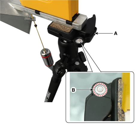
Using the level bubble (B) of the tripod [SST No.: 09964-C1300] (A), set the reflector horizontally.
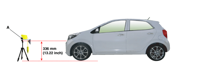
Set the height of the SCC calibration reflector [SST No.: 09964-C1100] (A) to 336 mm (13.22 in.).
Visually check the radar sensor and front bumper surface again for the following.
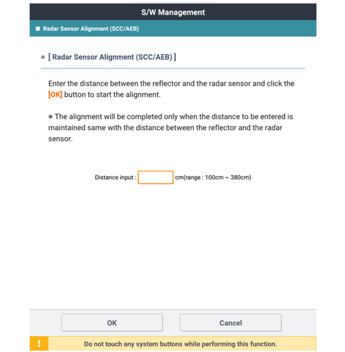
Connect the KDS/GDS to the vehicle DLC and start the sensor alignment.
After selecting the correct vehicle model, select "FCA Alignment" from the auxiliary functions in the KDS menu.
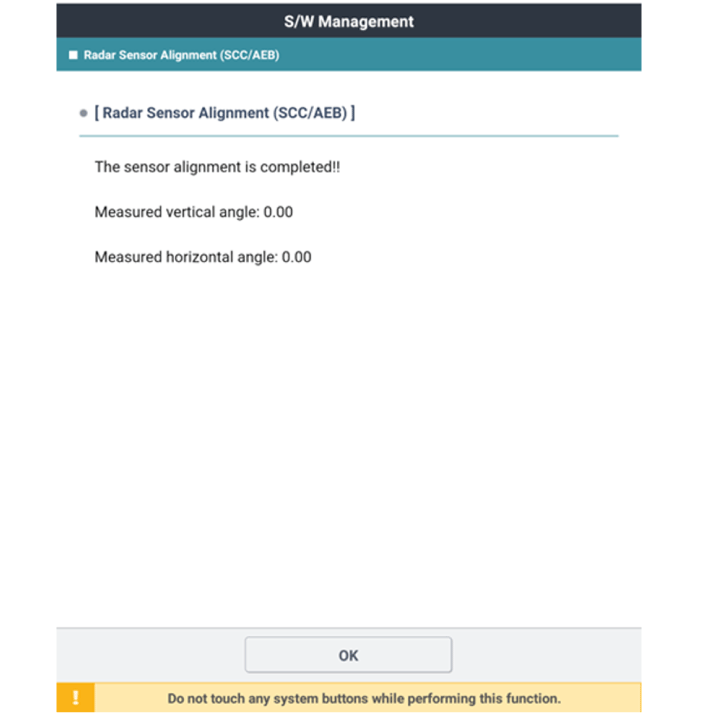
Perform sensor alignment as shown on the KDS monitor.
Enter the distance between the reflector and the radar sensor.
Check the radar sensor alignment value. Specification: Vertical angle: -1.6 to -2.4°; Horizontal angle: -0.8 to +0.8°
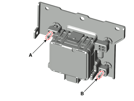
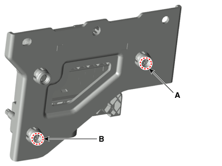
If the vertical alignment is outside the allowable range, turn the adjusting screw (A) or the vertical adjusting screw (B) until the alignment is within tolerance. Specification: Vertical angle: -1.6 to -2.4°; Horizontal angle: -0.8 to +0.8° [Front][Rear]
?
Test yourself
A quick Kia Picanto JA quiz: every answer comes with an explanation and a link to the manual page.