Intermediate Sensor Inspection [FS5 A EL]
1. Inspect the power supply circuit for the intermediate sensor.
a. Set the battery component (ex: battery, battery tray and PCM component) out of the way.
b. Disconnect the intermediate sensor connector.
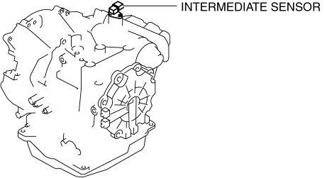
c. Switch the ignition to ON (engine off).
d. Measure the voltage at intermediate sensor connector terminal A (harness-side).
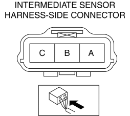
If there is any malfunction, repair wiring harness between intermediate sensor and AT main relay.
- Intermediate sensor specification
B+
e. Switch the ignition to off.
f. Connect the intermediate sensor connector.
2. Inspect the GND circuit for the intermediate sensor.
a. Switch the ignition to off.
b. Measure the voltage at intermediate sensor connector terminal C (harness-side).
If there is any malfunction, repair wiring harness between intermediate sensor and GND.
- Intermediate sensor specification
Below 1.0 V
3. Inspect the signal circuit for the intermediate sensor.
a. Connect the oscilloscope to the following TCM connector terminals and set it as below.
(+) lead: TCM terminal AC
(-) lead: battery negative terminal
Oscilloscope setting: 1 V/DIV (Y), 200 μs/DIV (X), DC range
b. Start the engine.
c. Measure the wave form when the following conditions are met.
Gear position: 3GR
Vehicle speed: 30 km/h {19 mph}
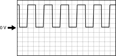
If there is any malfunction, replace the intermediate sensor..
Test yourself
A quick Mazda 3 quiz: every answer comes with an explanation and a link to the manual page.