TCM Inspection [FS5 A EL]
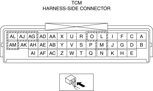
The TCM terminal voltage can vary with conditions when measuring and changes due to age deterioration on the vehicle, causing false diagnosis. Therefore a comprehensive inspection of the input and output systems, and the TCM is necessary to determine where the malfunction occurs.
1. Connect the voltmeter (-) lead to body GND.
2. Measure the voltage at each terminal.
If any incorrect voltage is detected, inspect the related system(s), wiring harnesses and connector(s) referring to the “Inspection Item” column in the “TCM Terminal Voltage”.
Terminal |
Connected to |
Test Condition |
Voltage (V) |
Inspection Item |
A |
— |
— |
— |
— |
B |
CAN module |
Because this terminal is for CAN, no valid determination of terminal voltage is possible. |
||
C |
— |
— |
— |
— |
D |
— |
— |
— |
— |
E |
CAN module |
Because this terminal is for CAN, no valid determination of terminal voltage is possible. |
||
F |
Down switch |
Selector lever down-shift position |
Below 1.0 |
|
Except selector lever down-shift position |
B+ |
|||
G |
Up switch |
Selector lever up-shift position |
Below 1.0 |
|
Except selector lever up-shift position |
B+ |
|||
H |
— |
— |
— |
— |
I |
AT main relay |
Ignition switch off |
Below 1.0 |
|
Ignition switch ON |
B+ |
|||
J |
Battery |
Under any condition |
B+ |
|
K |
M position switch |
M position |
Below 1.0 |
|
Except M position |
B+ |
|||
L |
GND |
Under any condition |
Below 1.0 |
|
M |
GND |
Under any condition |
Below 1.0 |
|
N |
— |
— |
— |
— |
O |
AT main relay |
Ignition switch off |
Below 1.0 |
|
Ignition switch ON |
B+ |
|||
P |
AT main relay |
Ignition switch off |
Below 1.0 |
|
Ignition switch ON |
B+ |
|||
Q |
— |
— |
— |
— |
R |
— |
— |
— |
— |
S |
Oil pressure switch |
1GR |
Below 1.0 |
|
2GR |
Below 1.0 |
|||
3GR |
Below 1.0 |
|||
4GR |
B+ |
|||
5GR |
B+ |
|||
T |
— |
— |
— |
— |
U |
TR switch |
Selector lever at P position |
4.3—4.8 |
|
Selector lever at R position |
3.8—4.2 |
|||
Selector lever at N position |
3.0—3.5 |
|||
Selector lever at D position |
2.2—2.7 |
|||
Selector lever at M position |
2.2—2.7 |
|||
V |
TR switch, TFT sensor |
Under any condition |
Below 1.0 |
|
W |
— |
— |
— |
— |
X |
— |
— |
— |
— |
Y |
Input/turbine speed sensor (-) |
(See Input/turbine speed sensor.) |
|
|
Z |
VSS |
(See VSS.) |
|
|
AA |
TFT sensor |
ATF temperature 20 °C {68 °F} |
Approx.3.3 |
|
ATF temperature 65 °C {149 °F} |
Approx.1.3 |
|||
AB |
Input/turbine speed sensor (+) |
(See Input/turbine speed sensor.) |
|
|
AC |
Intermediate sensor |
(See Intermediate sensor.) |
|
|
AD |
Pressure control solenoid A (+) |
(See Pressure control solenoid A (+).) |
|
|
AE |
Pressure control solenoid A (-) |
(See Pressure control solenoid A (-).) |
|
|
AF |
— |
— |
— |
— |
AG |
Shift solenoid A |
(See Shift solenoid A.) |
|
|
AH |
Shift solenoid D |
1GR at D position |
Below 1.0 |
|
2GR at D position |
Below 1.0 |
|||
3GR at D position |
Below 1.0 |
|||
4GR at D position |
B+ |
|||
5GR at D position |
B+ |
|||
AI |
Shift solenoid F |
1GR at D position |
B+ |
|
2GR at D position |
B+ |
|||
3GR at D position |
B+ |
|||
4GR at D position |
B+ |
|||
5GR at D position |
Below 1.0 |
|||
AJ |
Shift solenoid B |
(See Shift solenoid B.) |
|
|
AK |
Shift solenoid E |
TCC released |
Below 1.0 |
|
TCC engaged |
B+ |
|||
AL |
Shift solenoid C |
(See Shift solenoid C.) |
|
|
AM |
Pressure control solenoid B |
(See Pressure control solenoid B.) |
|
|
Input/Output Wave From (Reference) Shift solenoid A
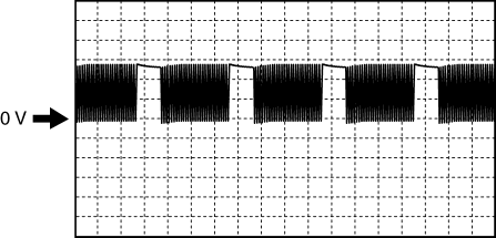
- TCM terminals
AG (+)—body GND (-)
- Oscilloscope setting
5 V/DIV (Y), 5 ms/DIV (X), DC range
- Test Condition
The following conditions are met:
Selector lever position: D position
Gear position: 4GR
- TCM terminals
AJ (+)—body GND (-)
- Oscilloscope setting
5 V/DIV (Y), 5 ms/DIV (X), DC range
- Test Condition
The following conditions are met:
Selector lever position: D position
Gear position: 1GR
- TCM terminals
AL (+)—body GND (-)
- Oscilloscope setting
5 V/DIV (Y), 5 ms/DIV (X), DC range
- Test Condition
The following conditions are met:
Selector lever position: D position
Gear position: 1GR
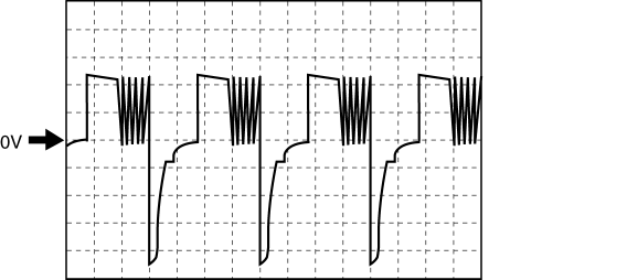
- TCM terminals
AM (+)—body GND (-)
- Oscilloscope setting
5 V/DIV (Y), 5 ms/DIV (X), DC range
- Test Condition
Shifting from 4GR to 5GR or from 5GR to 4GR
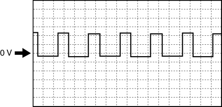
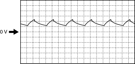
- TCM terminals
AD (+)—body GND (-)
- Oscilloscope setting
5 V/DIV (Y), 1 ms/DIV (X), DC range
- Test Condition
The following conditions are met:
Switch the ignition to ON (engine off)
Selector lever position: P position
Accelerator pedal fully depressed
- TCM terminals
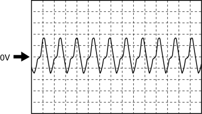
AE (+)—body GND (-)
- Oscilloscope setting
200 mV/DIV (Y), 1 ms/DIV (X), DC range
- Test Condition
The following conditions are met:
Switch the ignition to ON (engine off)
Selector lever position: P position
Accelerator pedal fully depressed
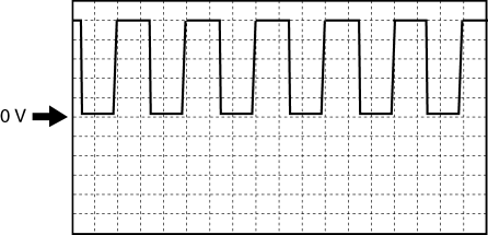
- TCM terminals
AB (+)—Y (-)
- Oscilloscope setting
1 V/DIV (Y), 2 ms/DIV (X), DC range
- Test Condition
Idle at P position after warm-up
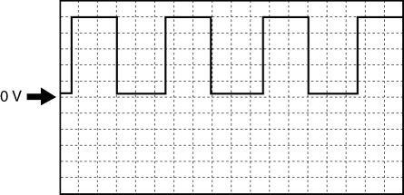
- TCM terminals
AC (+)—body GND (-)
- Oscilloscope setting
1 V/DIV (Y), 200 µs/DIV (X), DC range
- Test Condition
The following conditions are met:
Gear position: 3GR
Vehicle speed: 30 km/h {19 mph}
- TCM terminals
Z (+)—body GND (-)
- Oscilloscope setting
1 V/DIV (Y), 2 ms/DIV (X), DC range
- Test Condition
The following conditions are met:
Gear position: 3GR
Vehicle speed: 30 km/h {19 mph}
Test yourself
A quick Mazda 3 quiz: every answer comes with an explanation and a link to the manual page.