Specifications
Air conditioning is standard equipment on the B-Class. There are two versions: the first, called Thermatic (semi-automatic), and the second, available as an option, called Thermotronic (automatic), which provides multi-zone air distribution.
Air conditioning circuits
CABIN AIR FILTER
The cabin filter is located in the center of the cowl grille and is accessible after opening the engine hood.
COMPRESSOR
Compressor driven from the crankshaft by a multi-rib belt shared with all accessories.
COMPRESSOR BELT
Belt with automatic tensioner pulley, driving the air conditioning compressor, water pump and alternator from the crankshaft.
Dimensions (mm):
- without air conditioning: 17.80 x 1310.
- with air conditioning: 17.80 x 1745.
Air conditioning control
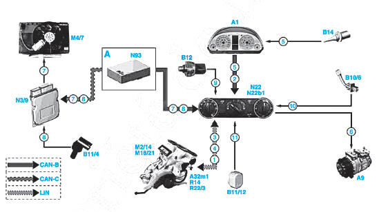
Thermatic air conditioning block diagram
CAN-B. Cabin CAN bus
CAN-C. Engine compartment CAN bus
Signals:
- PTC auxiliary heater control
- Speed signal
- Blower regulator control
- Air flap servomotor control
- Outside temperature
- Refrigerant compressor control
- Suction fan control
- Coolant temperature
- Refrigerant pressure
- Evaporator temperature
- Dew point / humidity level.
Components:
A1. Instrument cluster
A9. Refrigerant compressor
A32m1. Blower motor
B10/6. Evaporator temperature sensor
B11/4. Coolant temperature sensor
B11/12. Dew point sensor
B12. Refrigerant pressure transmitter
B14. Outside temperature sensor
M2/14. Mix air flap servomotor
M4/7. Suction fan motor and air conditioner with integrated control
M16/21. Fresh air and recirculated air flap servomotor
N3/9. CDI control unit
N22. KLA control panel
N22b1. Cabin air temperature sensor
N93. Central gateway control unit
R14. Blower motor series resistor block
R22/3. PTC auxiliary heater.
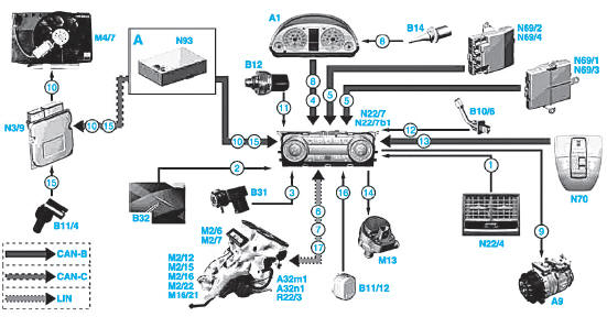
THERMOTRONIC air conditioning block diagram
CAN-B. Cabin CAN bus
CAN-C. Engine compartment CAN bus
Signals:
- Rear nozzle wheel position
- Solar radiation intensity
- Harmful substances
- Speed signal
- Window position
- Blower regulator control
- Air flap servomotor control
- Outside temperature
- Refrigerant compressor control
- Suction fan control
- Refrigerant pressure
- Evaporator temperature
- Louvered roof position
- Coolant circulation pump activation
- Coolant temperature
- Dew point / humidity level
- PTC auxiliary heater control.
Components:
A1. Instrument cluster
A9. Refrigerant compressor
A32m1. Blower motor
A32n1. Blower controller
B10/6. Evaporator temperature sensor
B11/4. Coolant temperature sensor
B11/12. Dew point sensor
B12. Refrigerant pressure transmitter
B14. Outside temperature sensor
B31. Harmful substance sensor
B32. Solar sensor
M2/6. Left mixer flap actuator
M2/7. Right mixer flap actuator
M2/12. Rear blocking flap actuator
M2/15. Left and right footwell ventilation actuator
M2/16. Left and right defrost flap actuator
M2/22. Center nozzle flap actuator
M4/7. Blower motor and integrated air conditioning control
M13. Coolant circulation pump
M16/21. Fresh air and recirculated air flap actuator
N3/9. CDI control module
N22/4. Rear blower electronic selector
N22/7. Air conditioning control panel and control module
N22/7b1. Cabin air temperature sensor
N69/1. Front left door control module
N69/2. Front right door control module
N69/3. Rear left door control module
N69/4. Rear right door control module
N70. Roof control unit control module
N93. Central gateway control module
R22/3. PTC auxiliary heater.
THERMOTRONIC AIR CONDITIONING COMPONENTS: SPECIFICATIONS AND LOCATION
ACTUATORS
The actuators are located on the heater housing (Fig.1).
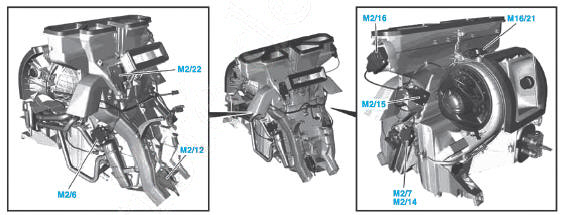
Actuator locations Fig. 1
M2/6. Left mixer flap actuator *
m2/7. Right mixer flap actuator *
m2/12. Rear blocking flap actuator *
m2/14. Mixed air flap actuator
m2/15. Left and right footwell ventilation actuator *
m2/16. Left and right defrost flap actuator *
m2/22. Center nozzle flap actuator *
m16/21. Fresh air or recirculated air flap actuator.
* THERMOTRONIC air conditioning only.
BLOWER MOTOR
The control module controls the blower motor speed in 5 stages via the resistor pack (Fig.2).
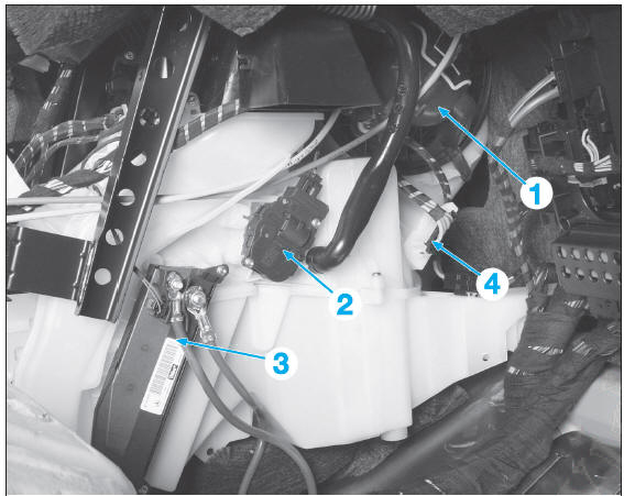
Fig. 2
- Blower motor
- Mixed air flap actuator
- PTC heater
- Resistor pack.
AIR CONDITIONING PRESSURE SWITCH
The refrigerant pressure transmitter is located on the receiver-drier (Fig.3).
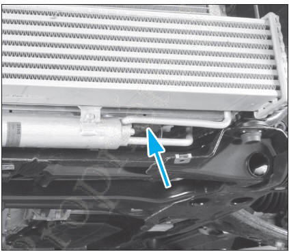
Fig. 3
EVAPORATOR TEMPERATURE SENSOR
The evaporator temperature sensor is located behind the evaporator, on the left in the air conditioning housing (Fig.4).
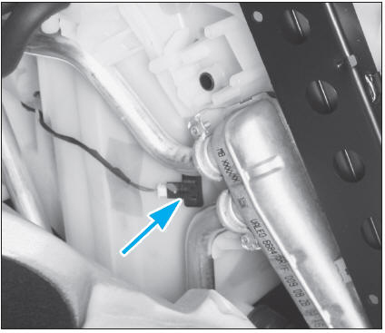
Fig. 4
THERMOTRONIC AIR CONDITIONING CONTROL MODULE
The control module is integrated into the air conditioning control unit. It also incorporates the cabin air temperature sensor and its blower fan.
Pin assignment of the 3 air conditioning control module connectors (Fig.5)
| 18-way connector | |
| Pins | Assignments |
| 1 | Ground |
| 2 | Air conditioning pressure sensor ground |
| 3 | Hazard warning switch ground |
| 4 | Passenger child seat automatic detection indicator (optional) |
| 5 | Hazard warning switch power supply |
| 6 | Hazard warning switch indicator |
| 9 | Air conditioning pressure sensor signal |
| 10 | Passenger compartment CAN bus high line |
| 11 | Passenger compartment CAN bus low line |
| 12 | Compressor clutch ground |
| 13 | Compressor clutch power supply |
| 14 | Power supply via fuse 5 |
| 17 | Air conditioning pressure sensor power supply |
| Unused pins: 7, 8, 15, 16 and 18 | |
| 12-way connector | |
| 2 | Evaporator temperature sensor signal |
| 3 | LIN communication bus to PTC auxiliary heater |
| 4 | Mixed air flap actuator ground |
| 5 | PTC auxiliary heater power supply |
| 7 | Fresh or recirculated air flap actuator |
| 8 | Fresh or recirculated air flap actuator |
| 9 | LIN communication bus to mixed air flap actuator |
| 10 | Evaporator temperature sensor ground |
| 11 | Mixed air flap actuator power supply |
| Unused pins: 1, 6 and 12 | |
| 5-way connector | |
| 1 | Blower power supply |
| 2 | Blower power supply |
| 3 | Blower power supply |
| 4 | Blower power supply |
| 5 | Ignition-switched power supply via fuse 10 |
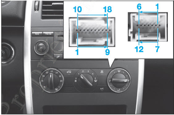
Air conditioning control module pinout Fig. 5
Test yourself
A quick Mercedes-Benz B-Class quiz: every answer comes with an explanation and a link to the manual page.