Suspension - axles - geometry
Removal and installation of a rear suspension element
In this manual: Suspension - axles - geometry
31steps
~186min
4/5difficulty
Done 0 of 31
SHOCK ABSORBER
REMOVAL
In the luggage compartment
- Open the left-hand side storage compartment or the right-hand load-floor trim, depending on the shock absorber to be removed.
- Remove the nut (1) (Fig.22).
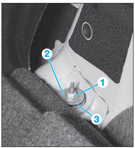
Fig. 22
- Remove the washer (2) and the rubber mount (3).
Under the vehicle
- Raise and support the vehicle, rear wheels hanging free.
- Remove the rear wheel on the relevant side.
- Remove the nut (4), then the bolt (5) (Fig.23).
- Compress the shock absorber (6) in order to remove it.
INSTALLATION
Refit in the reverse order of removal, observing the following points:
- replace the nuts (1) and (4),
- observe the specified tightening torques.
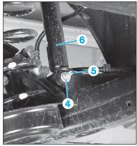
Fig. 23
SPRINGS
REMOVAL
- Raise and support the vehicle, rear wheels hanging free.
- Remove the rear wheel on the relevant side.
- Fit a spring compressor.
- Compress the spring until it can be removed.
- Remove the suspension springs.
INSTALLATION
Carry out the removal steps in reverse order, observing the spring fitting direction.
STABILIZER BAR
REMOVAL
- Under the vehicle, remove the right-hand rear undertray as well as the rear axle guard.
- On each side, remove (Fig.24):
- the attachment (1) of the anti-roll bar link (2) to the rear axle,
- the mounting bolts (3) of the bracket (4).
- Remove the anti-roll bar (5).
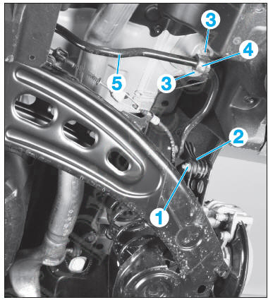
Fig. 24
INSTALLATION
Carry out the removal steps in reverse order, observing the specified tightening torques.
REAR AXLE
REMOVAL
- Raise and support the vehicle on a two-post lift.
- Remove the rear wheels.
- On each side:
- disconnect the connector (1) of the speed sensor at the wheel arch (Fig.25),
- remove the springs (see relevant operation).
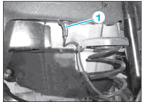
Fig. 25
- Loosen the lock nut (2) of the parking brake adjustment (Fig.26) until the cables (3) and (4) can be unhooked.
- On each side:
- without opening the brake circuit, remove the brake calipers and hang them from the body (see operation in the 'BRAKES' chapter),
- remove the anti-roll bar links (5) from the rear axle (Fig.27).
- Remove the rear axle guard, then place a support device under the rear axle in its place.
- Remove (Fig.28):
- the coupling mount (6) of the rear axle,
- the shock absorbers (7) of the rear axle on each side,
- remove the bolt (8) and the plate (9).
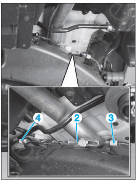
Fig. 26
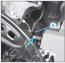
Fig. 27
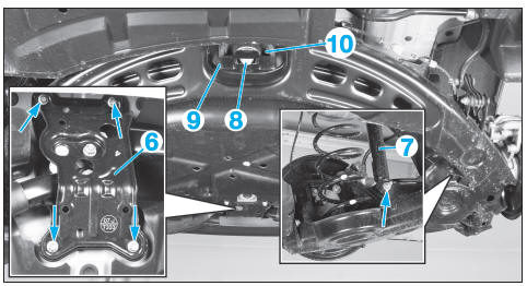
Fig. 28
- Slowly lower the rear axle.
INSTALLATION
- Inspect the centre bearing (10) and replace it if necessary.
- Check the length of the bolt (8).
 Original bolt: M16 x 1.5 x 180.
Repair bolt: M16 x 1.5 x 225 and cage nut.
- If the original bolt (8) is reused:
- screw an M16 x 1.5 tap in place of the bolt (8),
Do not exceed a torque of approx. 5 N.m; fit a repair bolt if the torque is exceeded or if swarf is formed.- position the rear axle,
- replace the bolt (8) and then tighten it,
Caution:
Do not use an impact wrench.
- refit the shock absorbers,
- refit the coupling mount (6) of the rear axle,
- continue refitting in the reverse order of removal.
- If a repair bolt is used (Fig.29):
 The repair bolt must be fitted from the passenger compartment, and the original cage nut must be replaced.
- remove the rear seat,
- set the carpet aside and remove the access cover,
- mark the recess (11) in the rear floor (12), then cut it out,
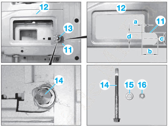
Fig. 29
- 10 mm
- 58 mm
- 42 mm
- 24 mm.
- using a Ø 17 mm drill, drill out the damaged thread of the centre bearing and clean the hole,
- apply anti-corrosion protection,
- clean the bearing surfaces of the bracket (13) on the bearing side and on the bolt side,
- position the rear axle,
- centre the bearing body in the body and press it against it,
- insert the repair bolt (14) from above,
- position the washer (15) and then the nut (16),
- tighten the nut (16),
Do not use an impact wrench.- refit the shock absorbers,
- refit the coupling mount (6) of the rear axle,
- continue refitting in the reverse order of removal.
HUB
REMOVAL
- Remove the brake disc (see operation in the 'BRAKES' chapter).
- Remove the speed sensor (1) from the rear hub (Fig.30).
- Remove the bolts (2), then the rear hub.
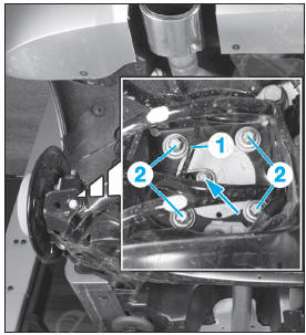
Fig. 30
INSTALLATION
Carry out the removal steps in reverse order, replacing the speed sensor bolt and the rear hub bolts.
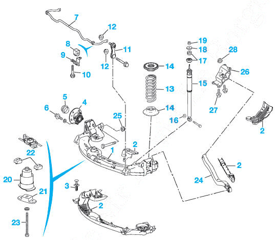
Suspension - Rear axle
- Rear axle
- Guards
- Clip
- Hub
- Cover
- Hub bolts (replace):
- 1st stage: 8 daN·m
- 2nd stage: loosen.
- 3rd stage: 12 daN·m
- Stabiliser bar
- Bearing
- Bracket
- Bolt (replace): 2.8 daN·m
- Stabiliser bar link
- Nut (replace): 4 daN·m
- Spring
- Strut mounts
- Shock absorber
- Nut (replace): 5 daN·m
- Strut bearing
- Washer
- Nut: 2 daN·m
- Centre bearing
- Thrust plate
- Strut bearing
- Original centre bearing bolt (replace):
- 1st stage: 20 daN·m
- 2nd stage: loosen.
- 3rd stage: 22 daN·m
- 4th stage: 90°.
- Check torque: 23 daN·m
- Radius arm
- Radius arm nut on rear axle: 8 daN·m
- Coupling bearing
- Rear axle coupling bearing to body bolt (replace):
- 1st stage: 6 daN·m
- 2nd stage: loosen.
- 3rd stage: 8 daN·m
- Tie rod nut on coupling bearing:
- 1st stage: 4 daN·m
- 2nd stage: loosen.
- 3rd stage: 3 daN·m
- 4th stage: 80°.
Test yourself
A quick Mercedes-Benz B-Class quiz: every answer comes with an explanation and a link to the manual page.
Was this page helpful?