Suspension - axles - geometry
Wheel alignment adjustment
In this manual: Suspension - axles - geometry
2steps
~12min
1/5difficulty
Done 0 of 2
PRELIMINARY OPERATIONS BEFORE CHECKING WHEEL ALIGNMENT
- Vehicle empty and in running order with full fluids (otherwise compensate with additional weights in the luggage compartment).
- Check the vehicle level at the front axle and rear axle using the inclinometer (Fig.1).
VEHICLE LEVELS - REQUIRED TOOLS
- [1]. Inclinometer with sensor (Fig.1).
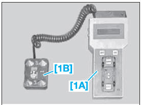
Fig. 1
[1A]. Inclinometer.
[1B]. Measuring sensor.
CHECK
- Prepare for axle alignment check.
 If the wheels have been lifted off the ground, bounce the vehicle firmly before taking measurements.
Front
- Place measuring sensor [1B] (Fig.2) on the lower control arm (1) and record the measured value at front left, then front right.
The sensor's electrical cable must face the front subframe of the vehicle.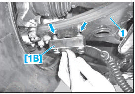
Fig. 2
- Compare the recorded values with the specified values (see 'SPECIFICATIONS').
- If the values are out of tolerance, correct the level by replacing the springs.
Rear
- Fold back the protective cover located under the left and right rear springs.
- Place measuring sensor [1B] (Fig.3) in the lower spring seat (2) and record the measured value at rear left, then rear right.
The sensor's electrical cable must face the front of the vehicle.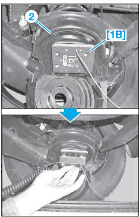
Fig. 3
- Compare the recorded values with the specified values (see 'SPECIFICATIONS').
- If the values are out of tolerance, correct the level by replacing the springs.
TOE
REQUIRED TOOLS
- [2]. Wheel jack (Fig.4).
FRONT TOE ADJUSTMENT
- Check the vehicle level and adjust it if necessary (see related operation).
- Position and lock the steering wheel in the centered position.
- Check that the steering gear is centered: the mark on the steering column must align with the mark on the steering gear (Fig.5).
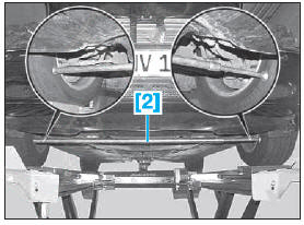
Fig. 4
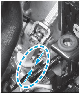 <.
Fig. 5
- Fit the wheel-pusher plate [2] (Fig.4).
Fitting the wheel jack simulates the vehicle being set in motion.- Check and adjust the toe if necessary (Fig.6).
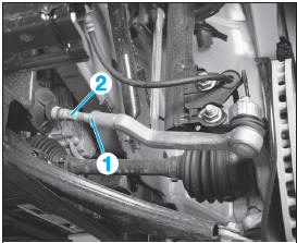
Fig. 6
- Locknut.
- Adjusting tie rod.
FRONT CASTER AND CAMBER
Adjusting the front axle caster also changes the front axle camber. When adjusting both camber and caster, adjust caster before camber.REQUIRED TOOLS
- [3]. Counter-support (ref. 169 586 00 03 00) (Fig.8).
CHECK AND ADJUSTMENT
Check
- Check:
- the vehicle height (see the relevant operation),
- the camber, compare with the values in the table (see 'SPECIFICATIONS'),
- the caster, compare with the values in the table.
Adjustment
- Remove the nuts (1) securing the ball joint (2) to the lower wishbone (3) (Fig.7).
- Loosen the nut (4).
- Adjust the caster.
- Replace the nuts (1) and tighten nuts (1) and (2) to the specified torque.
- Recheck the front vehicle height (see 'SPECIFICATIONS').
- Loosen the nuts (5) (Fig.8) until the strut leg (6) can be moved off the steering knuckle (7).
Hold the bolts (8) with tool [3].- Adjust the camber.
- Tighten the nuts (5) to the specified torque, starting with the upper nut.
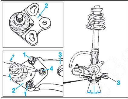
Fig. 7
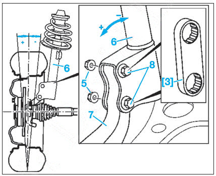
Fig. 8
Test yourself
A quick Mercedes-Benz B-Class quiz: every answer comes with an explanation and a link to the manual page.
Was this page helpful?