Suspension - axles - geometry
Removal and refitting of a front suspension element
In this manual: Suspension - axles - geometry
34steps
~204min
4/5difficulty
Done 0 of 34
SUSPENSION ELEMENT
REMOVAL AND REFITTING
- Raise and support the front of the vehicle with the wheels hanging free.
In the wheel arch
- Remove (Fig.9):
- the bracket (1) of the suspension element (2),
- the upper attachment (arrow) of the stabilizer bar link (3),
- the lower attachments (4) of the suspension element (2) to the steering knuckle (5).
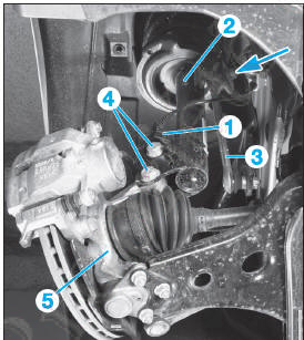
Fig. 9
In the engine compartment
- Remove the upper attachments (6) (Fig.10):
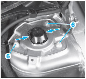
Fig. 10
- Compress the clips (arrows), then remove the suspension element through the wheel arch.
To refit, reverse the removal steps, observing the following points:
- always replace all self-locking screws and nuts,
- observe the specified tightening torques,
- check and, if necessary, adjust the front axle geometry (see the relevant operation).
DISASSEMBLY AND REASSEMBLY
 Note the order and orientation of the suspension element components for reassembly.
- Operation to be carried out on the workbench, suspension element removed.
- Clamp the suspension element in a vice fitted with soft jaws.
- Compress the suspension spring with a suitable spring compressor until the spring seats are free of pressure.
Make sure the spring compressor is suitable for the vehicle.- Remove (Fig.11):
- the cap (1),
- the strut rod nut (2),
The spring tension is very high, so the utmost care is essential when removing the strut rod nut.- the upper mount (3),
- the spring (4),
- the rubber bump stop (5),
- the rubber mount (6).
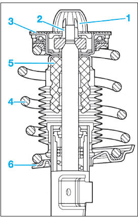
Fig. 11
To reassemble, reverse the disassembly steps, observing the following points:
- respect the order and orientation of the suspension element components noted during disassembly,
- make sure the spring is correctly seated on its spring seats,
- check the condition of all components and replace them if necessary.
STABILIZER BAR
REMOVAL - REFITTING
- Support the engine cooling radiator from above.
- Remove the air intake duct from the radiator.
- Raise and support the vehicle with the wheels hanging free.
- Remove the engine undertray.
- Remove the front wheels.
- Drain the coolant through the radiator.
- Remove the lower coolant hose from the radiator.
- Vehicle with automatic transmission: remove the oil line bracket at the bottom of the radiator.
- Raise the cooling fan bracket by 5 centimetres.
- Disconnect the stabilizer bar (1) from the links (2) (arrow) (Fig.12).
- Vehicle with xenon headlamps:
- disconnect the connector of the front left level sensor,
- remove the stabilizer bar level sensor bracket.
- Remove the screws (arrows) from the radiator support (3) (Fig.13).
- Remove the radiator support (3).
- On each side, remove the 2 screws (4), then the bracket (5) (Fig.12).
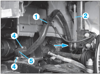
Fig. 12
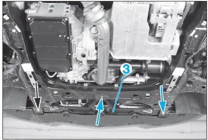
Fig. 13
- Lift the radiator and remove the stabilizer bar (1) from the front.
 Pivot the stabilizer bar (1) upward, pass it over the left and right brake hoses and remove it.
To refit, reverse the removal steps, observing the following points:
- Vehicle with xenon headlamps: check the headlamp position and adjust it if necessary,
- pay attention to the fitting position of the stabilizer bar mounts,
- the mating surfaces between the radiator support (3) and the subframe must be clean.
SUBFRAME
REMOVAL
- Remove:
- the wheel arches,
- the air filter housing.
- Position and lock the steering wheel in the centered position.
- Check the centre position of the steering gear: the mark on the steering column must align with the mark on the steering gear (Fig.14).
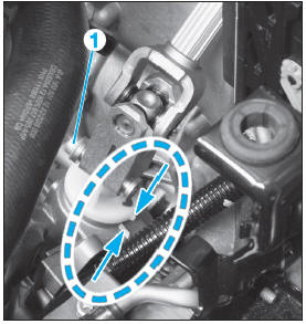
Fig. 14
- Remove the screw (1), then disconnect the steering column from the steering gear.
- Disconnect the two connectors from the power steering ECU.
- Remove the engine undertray.
- Secure the radiator.
- Set the coolant expansion tank aside without disconnecting its hoses.
- Using a workshop crane, lift the engine until the engine mounts are unloaded.
- On each side, remove:
- the bracket (2) of the stabiliser bar (3) and tie the stabiliser bar back (Fig.15),
- the steering track rod end from the steering knuckle.
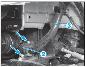
Fig. 15
- Remove the nuts securing the ball joint (4) to the lower arm (5) (Fig.16).
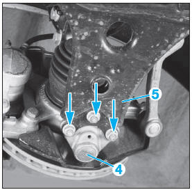
Fig. 16
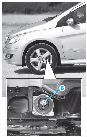
Fig. 17
- Place a support device under the subframe.
- Place another support device fitted with a wooden block under the oil sump.
- On each side, remove the bolt (6) from the mounts (Fig.17).
- Remove the nuts (7) (Fig.18).
- Remove the bolts (8).
- Slowly lower the subframe, lower arm and steering gear assembly.
 Before lowering the subframe, make sure no wiring harness, hose or pipe will obstruct its descent.
INSTALLATION
When refitting, observe the following points:
- when refitting the subframe, the lower arm ball joints must be inserted into the steering knuckles,
- bring all the subframe bolts (8) up to position, then tighten them,
- replace self-locking bolts or nuts,
- observe the tightening torques,
- check the front wheel alignment and adjust it if necessary.
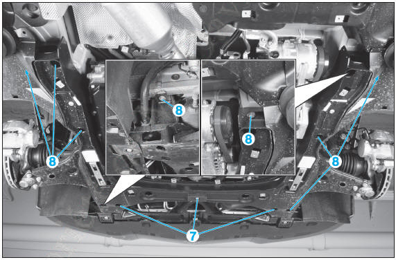
Fig. 18
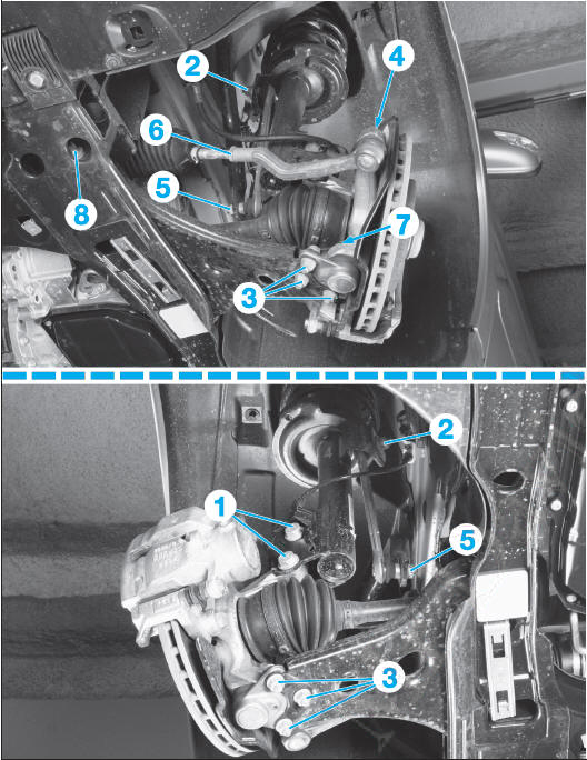
Attachments of the various components of a front suspension half-assembly
- Clamp bolt of the strut to the steering knuckle
- Attachment of the stabiliser bar link to the strut
- Attachment of the lower ball joint to the lower arm
- Steering track rod end nut to the steering knuckle
- Attachment of the stabiliser bar link to the stabiliser bar
- Steering track rod end locknut
- Lower ball joint nut to the steering knuckle
- Front attachment of the lower arm to the subframe.
LOWER ARM
REMOVAL
- Raise and support the vehicle with the wheels hanging free.
- Remove the front wheel on the relevant side.
- Remove:
- the engine undertray,
- the rear part of the front wheel arch.
- Remove (Fig.19):
- the bolts (arrows) securing the lower arm (1) to the subframe,
- the support (2),
- the nut (3) securing the lower ball joint to the steering knuckle, then remove the lower ball joint.
- Remove the lower arm (1) from the subframe.
INSTALLATION
When refitting, observe the following points:
- check the lower ball joint and the rubber bushings of the lower arm, and replace them if necessary,
- only tighten the lower arm-to-subframe bolts to torque when the vehicle is on its wheels and the steering has been turned fully left, then fully right,
- replace self-locking bolts or nuts,
- observe the tightening torques,
- check the front wheel alignment and adjust it if necessary.
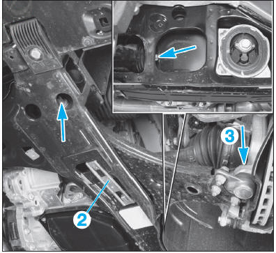
Fig. 19
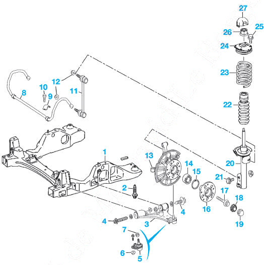
Suspension - front axle
- Subframe
- Bolts: 13 daN.m
- Lower arm
- Bolts:
- Step 1: 12 daN.m.
- 2nd stage: 90°.
- Lower ball joint
- Ball joint to arm fixing: 5.5 daN.m
- Ball joint to steering knuckle fixing (replace):
- Step 1: 6 daN.m.
- 2nd pass: 60°.
- Stabiliser bar
- Bracket
- Bolts: 2.8 daN.m
- Stabiliser bar link
- Bolts: 6 daN.m
- Steering knuckle
- Bearing
- Circlip
- Hub
- Driveshaft bolt (*):
- Step 1: 8 daN.m.
- 2nd stage: 90°.
- Driveshaft flanged nut:
- Step 1: 10 daN.m.
- 2nd pass: 60°.
- Cap
- Strut assembly
- Lower strut assembly attachment:
- Step 1: 12 daN.m.
- 2nd stage: 90°.
- Boot with bump stop
- Spring
- Top mount
- Shock absorber to body mounting bolts:
- Step 1: 2 daN.m.
- 2nd pass: 45°.
- Shock absorber rod nut (replace): 6.7 daN.m
- Cap.
STEERING KNUCKLE
REMOVAL
- Raise and support the vehicle with the wheels hanging free.
- Remove the front wheel on the relevant side.
- Depending on the fitting, loosen the flanged nut or the driveshaft bolt.
- Remove (Fig.20):
- the brake disc (1) (see operation in the 'BRAKES' chapter),
- the support (2) of the strut assembly (3), and set it aside,
- the steering track rod end (4) from the steering knuckle (5),
- the speed sensor from the steering knuckle,
- the nut (6) securing the lower ball joint to the steering knuckle, then remove the lower ball joint,
- the lower mountings (7) of the strut assembly (3).
- Remove the steering knuckle (5) from the driveshaft (8).
INSTALLATION
When refitting, observe the following points:
- replace self-locking bolts or nuts,
- observe the tightening torques,
- check the front wheel alignment and adjust it if necessary.
HUB BEARING
 Any bearing that has been removed must be replaced.
REQUIRED TOOLS
- Workshop press.
- [1]. Drift (Fig.21).
- [2]. Puller (Fig.21).
REPLACEMENT
 Operation to be carried out on the workbench, steering knuckle removed.
- Remove the circlip retaining the front hub bearing.
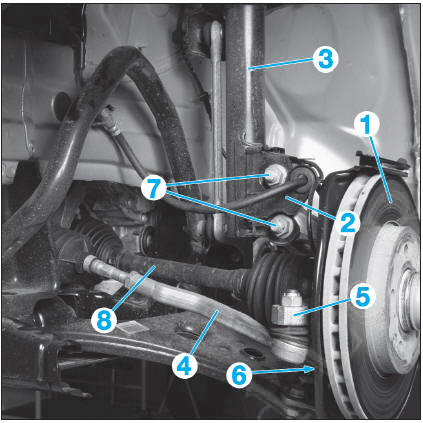
Fig. 20
- Position the steering knuckle (1) on a press.
- Drive the hub (2) out from below with a drift [1] (Fig.21).
- Remove the bearing (3) from below.
- Extract the inner bearing race from the hub (2) using the puller [2].
- When refitting, pay attention to the fitting position of the bearing (3). The marks (arrows) on the angular contact bearing (3) must face the inside of the hub carrier (1). If the bearing is fitted incorrectly, no pulse signal will be detected by the wheel speed sensor.
The wheel speed sensor tone ring is integrated into the bearing (3).
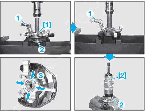
Fig. 21
Test yourself
A quick Mercedes-Benz B-Class quiz: every answer comes with an explanation and a link to the manual page.
Was this page helpful?