Interpreting XR25 bar graphs

INSTRUCTIONS Use test connector block Elé. 1332 for any work at the ECU connector.
| Ensure the XR25 tester is not the cause of the fault by trying to communicate with an ECU on another vehicle. If the XR25 tester is not at fault and communication cannot be established with any other ECU on the same vehicle, a faulty ECU may be disturbing diagnostic lines K and L. Disconnect components one after another to locate this ECU. Check that the ISO interface is in position S8, that you are using the latest XR25 cassette version and the correct access code (D34). Check the battery voltage and carry out the necessary work to obtain a correct voltage (battery U > 10.5 volts). |
| Check that the 15 ampere fuses in the engine interconnection box are not blown (positions 3 and 4). Check the connection and condition of the connectors at the ECU connector and the engine / dashboard connection R67. Check that the ECU is correctly supplied:
|
Check that the diagnostic socket is correctly supplied:
Check and ensure continuity and isolation of the lines of the diagnostic socket / ECU link:
|
| If diagnosis still cannot be established after these checks, replace the ECU (see the "help" chapter for this procedure). |
AFTER REPAIR Once communication is established, deal with any fault bar graphs that are lit.

INSTRUCTIONS None
Replace the ECU (see the "help" chapter for this procedure).
AFTER REPAIR Clear the ECU fault memory (G0**), switch off the ignition, then carry out a road test.
Finish the job with a check using the XR25 diagnostic tool.

INSTRUCTIONS Use test connector block Elé. 1332 for any work at the ECU connector.
co.1
NOTES If bar-graph indicators 2D and 3G are also lit steadily, look for a short to ground on the sensor ground (pin 3 of the ECU connector).
Also check the condition and tightness of the GMP earth strap and the engine-to-gearbox earth strap.
Check continuity and insulation from +12 V of the following circuit:
Check continuity of the following circuit:
Check the connectors at both ends. |
| If the fault persists after these checks, replace the coolant temperature sensor, then clear the ECU fault memory. If the "coolant temperature sensor circuit" fault reappears, replace the ECU (refer to the "help" chapter for this procedure). |
cc.0
INSTRUCTIONS None
Check insulation from ground of the following circuit:
Check whether the sensor circuit (or the sensor) is short-circuited (resistance at 60 °C = 1.2 kOhms). Check both connectors. |
| If the fault persists after these checks, replace the coolant temperature sensor, then clear the ECU fault memory. If the "coolant temperature sensor circuit" fault reappears, replace the ECU (refer to the "help" chapter for this procedure). |
AFTER REPAIR Clear the ECU fault memory (G0**), switch off the ignition, then carry out a road test.
Finish the job with a check using the XR25 diagnostic tool.

INSTRUCTIONS Use test connector block Elé. 1332 for any work at the ECU connector.
co.1
NOTES If bar-graph indicators 2G and 3G are also lit steadily, look for a short to ground on the common sensor ground (pin 3 of the ECU connector).
Check continuity and insulation from +12 V of the following circuit:
Check continuity of the following circuit:
Check both connectors. |
| If the fault persists after these checks, replace the intake air temperature sensor, then clear the ECU fault memory. If the "intake air temperature sensor circuit" fault reappears, replace the ECU (refer to the "help" chapter for this procedure). |
cc.0
NOTES
Check insulation from ground of the following circuit:
Check whether the sensor circuit (or the sensor) is short-circuited (resistance at 20 °C = 3.5 kOhms). Check both connectors. |
| If the fault persists after these checks, replace the intake air temperature sensor, then clear the ECU fault memory. If the "intake air temperature sensor circuit" fault reappears, replace the ECU (refer to the "help" chapter for this procedure). |
AFTER REPAIR Clear the ECU fault memory (G0**), switch off the ignition, then carry out a road test.
Finish the job with a check using the XR25 diagnostic tool.

NOTES Use breakout box Elé. 1332 for any work at the ECU connector.
co.0
INSTRUCTIONS None
| Check continuity and insulation from ground of the circuit between pin 23 of the ECU connector and pin 3 of the pump connector (10-way). Also check insulation of this circuit from the circuit between pin 3 of the ECU connector and pin 5 of the pump connector (potentiometer ground). Also check continuity of the circuit between pin 4 of the ECU connector and pin 4 of the pump connector. Check for a possible short circuit of the potentiometer (between pins 4 and 5 of the 10-way connector) or of its supply. Check both connectors. |
| If the fault persists after these checks, replace the load potentiometer (refer to the replacement procedure in the "help" chapter). If the "load potentiometer circuit" fault reappears, replace the ECU (refer to the "help" chapter for this procedure). |
cc.1
NOTES If bar-graph indicators 2G and 2D are also lit, look for a short to ground on the sensor ground (pin 3 of the ECU connector).
| Check insulation from +5 V and +12 V of the circuit between pin 23 of the ECU connector and pin 3 of the pump connector (10-way). Also check insulation of this circuit from the circuit between pin 4 of the ECU connector and pin 4 of the pump connector (+5 V potentiometer supply). Check continuity of the circuit between pin 3 of the ECU connector and pin 5 of the pump connector. Check both connectors. |
| If the fault persists after these checks, replace the load potentiometer (refer to the replacement procedure in the "help" chapter). If the "load potentiometer circuit" fault reappears, replace the ECU (refer to the "help" chapter for this procedure). |
AFTER REPAIR Clear the ECU fault memory (G0**), switch off the ignition, then carry out a road test.
Finish the job with a check using the XR25 diagnostic tool.

dEF
INSTRUCTIONS None
Check insulation (from +12 V and from ground) of the following circuit:
|
| If the fault persists after these checks, replace the load potentiometer (refer to the replacement procedure in the "help" chapter). If the "load potentiometer circuit" fault reappears, replace the ECU (refer to the "help" chapter for this procedure). |
AFTER REPAIR Clear the ECU fault memory (G0**), switch off the ignition, then carry out a road test.
Finish the job with a check using the XR25 diagnostic tool.

NOTES The engine speed sensor circuit fault is present if the bar-graph indicator stays lit steadily with the engine running.
Use breakout box Elé. 1332 for any work at the ECU connector.
| Measure the resistance of the flywheel signal sensor at its connector. Replace the sensor if the resistance is not approximately 250 ohms. Check continuity and insulation of the following circuits:
Also check insulation between these 2 circuits. Check both connectors. Visually inspect the general condition of the wiring and its routing for risks of interference. |
| Check the position and condition of the sensor. Check the condition of the target (deformation, mounting, noise....). Check that the target conforms: 2 slots at 180°. |
| If the fault persists after these checks, replace the flywheel signal sensor. If the "flywheel signal sensor circuit" fault reappears, replace the ECU (refer to the "help" chapter for this procedure). |
AFTER REPAIR Clear the ECU fault memory (G0**), switch off the ignition, then carry out a road test.
Finish the job with a check using the XR25 diagnostic tool.

NOTES The vehicle speed sensor circuit fault is present if the bar-graph indicator stays lit steadily during a road test. Use breakout box Elé. 1332 for any work at the ECU connector.
cc.0
INSTRUCTIONS None
| Check insulation from ground of the circuit between pin 12 of the ECU connector and pin B1 of the vehicle speed sensor connector. Also check insulation of this circuit from the circuit between pin 3 of the ECU connector and pin B2 of the vehicle speed sensor connector. Check both connectors. Check the supply of the vehicle speed sensor:
|
| If the fault persists after these checks, replace the vehicle speed sensor, then clear the ECU fault memory. If the "vehicle speed sensor circuit" fault reappears, replace the ECU (refer to the "help" chapter for this procedure). |
co.1
NOTES
| Check the continuity and insulation from 12 volts of the wire between ECU connector pin 12 and vehicle speed sensor connector pin B1. Also check that this wire is insulated from the +APC supply line of the vehicle speed sensor (pin A of the sensor connector). Check both connectors. Check the supply of the vehicle speed sensor:
|
| If the fault persists after these checks, replace the vehicle speed sensor, then clear the ECU fault memory. If the "vehicle speed sensor circuit" fault reappears, replace the ECU (refer to the "help" chapter for this procedure). |
AFTER REPAIR Clear the ECU fault memory (G0**), switch off the ignition, then carry out a road test.
Finish the job with a check using the XR25 diagnostic tool.

INSTRUCTIONS None
Replace the ECU (refer to the "help" chapter for this procedure).
AFTER REPAIR Clear the ECU fault memory (G0**), switch off the ignition, then carry out a road test.
Finish the job with a check using the XR25 diagnostic tool.

NOTES The "needle lift sensor circuit" fault is present if the bargraph stays on steadily with the engine running. Use terminal block Elé. 1332 for any work at the ECU connector.
| Measure the resistance of the needle lift sensor at its connector. Replace the instrumented injector if the resistance is not approximately 105 ohms. Check the continuity of the following wires:
Check both connectors. |
| Check the insulation of the wire between ECU connector pin 7 and needle lift sensor connector pin 1. Check the insulation between the 2 needle lift sensor lines. |
| Also check the condition of the wiring between the sensor connector and the sensor. |
| The "needle lift sensor circuit" fault may be caused by the absence of injection in the instrumented cylinder. Check the condition of the injector and its fuel supply. |
| If the fault persists after these checks, replace the instrumented injector. If the "needle lift sensor circuit" fault reappears, replace the ECU (refer to the "help" chapter for this procedure). |
AFTER REPAIR Clear the ECU fault memory (G0**), switch off the ignition, then carry out a road test.
Finish the job with a check using the XR25 diagnostic tool.

NOTES Use breakout box Elé. 1332 for any work at the ECU connector.
co.0
INSTRUCTIONS None
| Measure the resistance of the altitude corrector relay coil (position H on the engine interconnection box). Check the continuity and insulation from ground of the wire between ECU connector pin 15 and relay socket corrector terminal 2. Check that +APC is present on relay socket pin 1 of the corrector. Check the connections at the ECU connector and at the relay socket. |
| If the fault persists after these checks, replace the altitude corrector relay. If the "altitude corrector circuit" fault reappears, replace the ECU (refer to the "help" chapter for this procedure). |
cc.1
NOTES Even if present at the time of checking, this fault will always be reported by a flashing BG 5D. To confirm that it is present, and therefore that the diagnosis below must be applied, clear the ECU memory, then activate actuator test mode G19*.
The fault is present if the bargraph flashes again.
| Measure the resistance of the altitude corrector relay coil (position H on the engine interconnection box). Replace the relay if the resistance is not approximately 85 ohms. Check the insulation from +12 volts of the wire between ECU connector pin 15 and relay socket corrector terminal 2. |
| If the fault persists after these checks, replace the altitude corrector relay. If the "altitude corrector circuit" fault reappears, replace the ECU (refer to the "help" chapter for this procedure). |
AFTER REPAIR Clear the ECU fault memory (G0**), switch off the ignition, then carry out a road test.
Finish the job with a check using the XR25 diagnostic tool.

INSTRUCTIONS Use test connector block Elé. 1332 for any work at the ECU connector.
co.0
INSTRUCTIONS None
| Measure the resistance of the advance corrector at the 10-pin pump connector (between pins 2 and 7). Replace the advance corrector if the resistance is not approximately 12 ohms. Check the continuity of the wire between ECU connector pin 6 and pump connector pin 7. Check that +APC is present on pin 2 of the corrector connector on the wiring side. Check the insulation from ground of the wire between ECU connector pin 6 and pump connector pin 7. Check both connectors. |
| If the fault persists after these checks, replace the advance corrector. If the "advance solenoid valve circuit" fault reappears, replace the ECU (refer to the "help" chapter for this procedure). |
cc.1
INSTRUCTIONS None
| Measure the resistance of the advance corrector at its 10-pin pump connector (between pins 2 and 7). Replace the advance corrector if the resistance is not approximately 12 ohms. Check the insulation from +12 volts of the wire between ECU connector pin 6 and pump connector pin 7. |
| If the fault persists after these checks, replace the advance corrector. If the "advance solenoid valve circuit" fault reappears, replace the ECU (refer to the "help" chapter for this procedure). |
AFTER REPAIR Clear the ECU fault memory (G0**), switch off the ignition, then carry out a road test.
Finish the job with a check using the XR25 diagnostic tool.

1.dEF
NOTES The fault is present if the bargraph stays on steadily with the engine running.
| This fault indicates seizure of the advance corrector, incorrect injection pump timing or a fuel supply problem. It is detected when the advance measured by the needle lift sensor differs by more than 5° from the advance setpoint requested by the ECU. NOTE: Seizure of the advance corrector causes a characteristic noise at key-on (irregular beat frequency of the corrector). |
|
AFTER REPAIR Clear the ECU fault memory (G0**), switch off the ignition, then carry out a road test.
Finish the job with a check using the XR25 diagnostic tool.

INSTRUCTIONS Use test connector block Elé. 1332 for any work at the ECU connector.
co.0
INSTRUCTIONS None
| Measure the resistance of the fast idle solenoid valve at its connector. Replace the fast idle solenoid valve if the resistance is not approximately 45 ohms. Check the continuity of the wire between ECU connector pin 16 and fast idle solenoid valve connector pin 1. Check that +APC is present on pin 2 of the fast idle solenoid valve connector on the wiring side. Check the insulation from ground of the wiring between pin 16 of the ECU connector and pin 1 of the fast idle solenoid valve connector. Check both connectors. |
| If the fault persists after these checks, replace the fast idle solenoid valve. If the "fast idle solenoid valve circuit" fault reappears, replace the ECU (refer to the "help" chapter for this procedure). |
cc.1
NOTE Even if present at the time of the check, this fault will always be reported by a flashing BG 6D. To confirm that it is present, and therefore that the diagnosis below must be carried out, erase the ECU memory, then run command mode G16*.
The fault is present if the bargraph flashes again.
| Measure the resistance of the fast idle solenoid valve at its connector. Replace the fast idle solenoid valve if the resistance is not approximately 45 ohms. Check the insulation from +12 volts of the wiring between pin 16 of the ECU connector and pin 1 of the fast idle solenoid valve connector. |
| If the fault persists after these checks, replace the fast idle solenoid valve. If the "fast idle solenoid valve circuit" fault reappears, replace the ECU (refer to the "help" chapter for this procedure). |
AFTER REPAIR Clear the ECU fault memory (G0**), switch off the ignition, then carry out a road test.
Finish the job with a check using the XR25 diagnostic tool.

INSTRUCTIONS Use test connector block Elé. 1332 for any work at the ECU connector.
co.0
INSTRUCTIONS None
| Measure the resistance of the EGR solenoid valve at its connector. Replace the EGR solenoid valve if the resistance is not approximately 45 ohms. Check the continuity of the wiring between pin 5 of the ECU connector and pin 1 of the EGR solenoid valve connector. Check for +APC on pin 2 of the EGR solenoid valve connector, wiring side. Check the insulation from ground of the wiring between pin 5 of the ECU connector and pin 1 of the EGR solenoid valve connector. Check both connectors. |
| If the fault persists after these checks, replace the EGR solenoid valve. If the "EGR solenoid valve circuit" fault reappears, replace the ECU (refer to the "help" chapter for this procedure). |
cc.1
NOTE Even if present at the time of the check, this fault will always be reported by a flashing BG 7D. To confirm that it is present, and therefore that the diagnosis below must be carried out, the engine must be started. The fault is present if the bar graph is steady on with the engine running.
| Measure the resistance of the EGR solenoid valve at its connector. Replace the EGR solenoid valve if the resistance is not approximately 45 ohms. Check the insulation from +12 volts of the wiring between pin 5 of the ECU connector and pin 2 of the EGR solenoid valve connector. |
| If the fault persists after these checks, replace the EGR solenoid valve. If the "EGR solenoid valve circuit" fault reappears, replace the ECU (refer to the "help" chapter for this procedure). |
AFTER REPAIR Clear the ECU fault memory (G0**), switch off the ignition, then carry out a road test.
Finish the job with a check using the XR25 diagnostic tool.

INSTRUCTIONS Use test connector block Elé. 1332 for any work at the ECU connector.
co.0
INSTRUCTIONS None
| Check the continuity and the insulation from ground of the wiring between pin 14 of the ECU connector and pin B1 of the relay box connector. Check for +APC on pin A1 of the relay box connector. Check both connectors. |
| If the fault persists after these checks, replace the relay box. If the "glow plug relay No. 1 control circuit" fault reappears, replace the ECU (refer to the "help" chapter for this procedure). |
cc.1
NOTE Even if present at the time of the check, this fault will always be reported by a flashing BG 8G. To confirm that it is present, and therefore that the diagnosis below must be carried out, erase the ECU memory, then activate command G10*1*.
The fault is present if the bargraph flashes again.
| Check the insulation from +12 volts of the wiring between pin 14 of the ECU connector and pin B1 of the relay box connector. Check both connectors. |
| If the fault persists after these checks, replace the relay box. If the "glow plug relay No. 1 control circuit" fault reappears, replace the ECU (refer to the "help" chapter for this procedure). |
AFTER REPAIR Clear the ECU fault memory (G0**), switch off the ignition, then carry out a road test.
Finish the job with a check using the XR25 diagnostic tool.

INSTRUCTIONS Use test connector block Elé. 1332 for any work at the ECU connector.
co.0
INSTRUCTIONS None
| Measure the resistance of the coil of the power steering electric pump relay (position C on the engine interconnection box). Replace the relay if the resistance is not approximately 65 ohms. Check the continuity and the insulation from ground of the wiring between pin 20 of the ECU connector and terminal 2 of the power steering electric pump relay socket. Check for +APC on terminal 1 of the power steering electric pump relay socket. Check the connections at the ECU connector and at the relay socket. |
| If the fault persists after these checks, replace the power steering electric pump relay. If the "power steering electric pump relay control circuit" fault reappears, replace the ECU (refer to the "help" chapter for this procedure). |
cc.1
NOTE Even if present at the time of the check, this fault will always be reported by a flashing BG 9D. To confirm that it is present, and therefore that the diagnosis below must be carried out, erase the ECU memory, then activate command mode G36*.
The fault is present if the bargraph flashes again.
| Measure the resistance of the coil of the power steering electric pump relay (position C on the engine interconnection box). Replace the relay if the resistance is not approximately 65 ohms. Check the insulation from +12 volts of the wiring between pin 20 of the ECU connector and terminal 2 of the power steering electric pump relay socket. |
| If the fault persists after these checks, replace the power steering electric pump relay. If the "power steering electric pump relay control circuit" fault reappears, replace the ECU (refer to the "help" chapter for this procedure). |
AFTER REPAIR Clear the ECU fault memory (G0**), switch off the ignition, then carry out a road test.
Finish the job with a check using the XR25 diagnostic tool.

NOTE Even if present at the time of the check, this fault will always be reported by a flashing BG 10G. To confirm that it is present, and therefore that the diagnosis below must be carried out, erase the ECU memory, then activate command G21*1*. The fault is present if the bar graph flashes again.
Use breakout box Elé. 1332 for any work at the ECU connector.
cc.1
INSTRUCTIONS None
Ensure isolation from 12 volts of the link between pin 18 of the ECU connector and the fault warning lamp on the instrument panel (pin 6 of connector MA).Check the fault warning lamp bulb (bulb short circuit).
AFTER REPAIR Clear the ECU fault memory (G0**), switch off the ignition, then carry out a road test.
Finish the job with a check using the XR25 diagnostic tool.

INSTRUCTIONS Use test connector block Elé. 1332 for any work at the ECU connector.
co.0
INSTRUCTIONS None
Check the condition of the glow plug warning lamp bulb and the presence of + APC at the lamp.Check the continuity and the insulation from ground of the wiring between pin 9 of the ECU connector and the glow plug warning lamp on the instrument panel (pin 5 of connector CY).
Check the connector at the ECU connector.
cc.1
NOTE Even if present at the time of the check, this fault will always be reported by a flashing BG 10D. To confirm that it is present, and therefore that the diagnosis below must be carried out, erase the ECU memory, then activate command G21*2*.
The fault is present if the bargraph flashes again.
Ensure isolation from 12 volts of the link between pin 9 of the ECU connector and the glow plug warning lamp on the instrument panel (pin 5 of connector CY).Check the glow plug warning lamp bulb (bulb short circuit).
AFTER REPAIR Erase the ECU memory (G0**), switch off the ignition, then carry out a road test.
Finish the job with a check using the XR25 diagnostic tool.

NOTE If necessary, carry out a complete check of the charging circuit using the Optima 5800 diagnostic station.
Carry out the necessary work to obtain a correct supply voltage to the ECU:8 volts < correct voltage < 16 volts.
- Battery charge check.
- Charging circuit check.
- Check the tightness and condition of the battery terminals.
- ECU ground check.
Check for +APC on pin 1 of the ECU connector.
AFTER REPAIR Clear the ECU fault memory (G0**), switch off the ignition, then carry out a road test.
Finish the job with a check using the XR25 diagnostic tool.

INSTRUCTIONS None
Carry out the learning of the accelerator pedal full-throttle position using command G31* (do not act directly on the load lever).Enter code G31* on the XR25 diagnostic tool keypad (engine speed zero).
- Press the accelerator pedal when the display flashes "PF".
The display then shows "good", "End", then "6/7.dIE" when the procedure has been completed correctly.
The right-hand bar graph 12 must be off. - Switch off the ignition.
AFTER REPAIR Clear the ECU fault memory (G0**), switch off the ignition, then carry out a road test.
Finish the job with a check using the XR25 diagnostic tool.

INSTRUCTIONS None
cc.1
NOTE Even if present at the time of the check, this fault will always be reported by a flashing BG 13G. To confirm its presence, and therefore the need to apply the diagnosis below, erase the ECU memory, then start the engine. The fault is present if the bar graph is on and flashing with the engine running.
| Check that the link between pin 19 of the ECU connector and pin 18 of the air conditioning control unit connector is isolated from 12 V. Check the connectors at both connectors (+ intermediate connection engine / dashboard). |
| If the fault persists after these checks, replace the air conditioning control unit. If the "air conditioning cut-out information" fault reappears, replace the diesel injection ECU (refer to the "Help" section for this procedure). |
AFTER REPAIR Clear the ECU fault memory (G0**), switch off the ignition, then carry out a road test.
Finish the job with a check using the XR25 diagnostic tool.
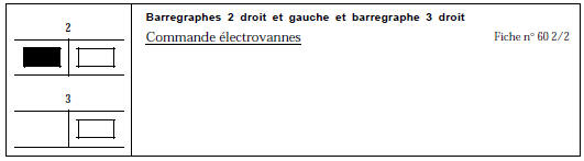
NOTE Without
These bar graphs show the control of the various solenoid valves:- Advance solenoid valve (bar graph 2 left is still on).
- Fast idle solenoid valve.
- EGR solenoid valve.

INSTRUCTIONS None

INSTRUCTIONS None
AFTER REPAIR Check that the bar graphs operate consistently.
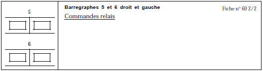
INSTRUCTIONS None
These bar graphs show the control of the various relays:- Preheating relay No. 1.
- Preheating relay No. 2 (not used).
- Power steering electric pump unit relay (if AC + PS).
- Altitude corrector relay.

NOTE If BG 9G is off when AC is requested, check the continuity and isolation of the link between pin 11 of the diesel ECU connector and pin 20 of the AC ECU connector.

INSTRUCTIONS None
AFTER REPAIR Check that the bar graphs operate consistently.

INSTRUCTIONS None

INSTRUCTIONS None

INSTRUCTIONS None
AFTER REPAIR Check that the bar graphs operate consistently.
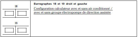
NOTE Vehicles fitted with power steering but without air conditioning must be configured as "without PS".
This bar graph indicates the ECU configuration in relation to the air conditioning and power steering with electric pump (GEP) options.ECUs sold by MPR are always configured for vehicles with air conditioning and with a power steering pump unit.
If the vehicle is not fitted with air conditioning, use command mode G50*4* to reverse the ECU configuration (the reverse command exists to configure "with AC": G50*3*).
If the vehicle is not fitted with the power steering electric pump unit (vehicle without air conditioning), use command mode G50*9* to reverse the ECU configuration (the reverse command exists to configure "with PS": G50*8*).
NOTE: Vehicles fitted with power steering but without air conditioning must be configured as "without PS".
AFTER REPAIR Clear the ECU fault memory (G0**), switch off the ignition, then carry out a road test.
Finish the job with a check using the XR25 diagnostic tool.
Test yourself
A quick Renault Kangoo quiz: every answer comes with an explanation and a link to the manual page.