Engine and peripherals
Diesel supply circuit
In this manual: Engine and peripherals
~2min read
K9K
Functional diagram of the diesel supply circuit
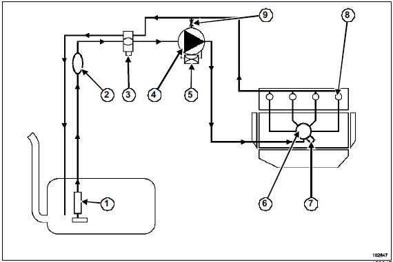
The circuit consists of:
- a gauge (1),
- a priming bulb (2),
- a fuel filter (3) that may be fitted with a water detection sensor,
- a high-pressure pump (4) incorporating a mechanical lift pump (transfer pump),
- a flow actuator (5),
- a fuel rail (6) fitted with a fuel pressure sensor (7),
- four solenoid injectors (8) fitted with relief valves,
- a venturi (9),
- various sensors,
- an injection control unit.
Never loosen a high-pressure pipe connection while the engine is running.
WARNINGIt is forbidden to:
- disassemble the inside of the pump and the injectors.
Only the flow actuator, the fuel temperature sensor and the venturi may be replaced,
- remove the fuel rail pressure sensor (to avoid contaminating the circuit).
If the pressure sensor fails, the pressure sensor, the rail and all five high-pressure pipes must be replaced.
F9Q
Functional diagram of the diesel supply circuit
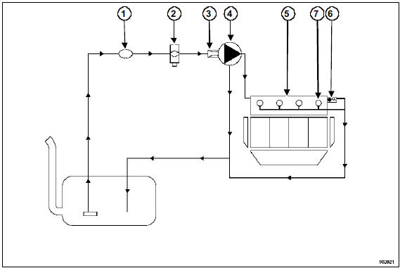
The circuit consists of:
- a priming bulb (1) (located in the engine compartment),
- a fuel filter (2) that may be fitted with a water detection sensor,
- a high-pressure regulator (3) mounted on the pump,
- a high-pressure pump (4),
- a fuel rail (5) fitted with a fuel pressure sensor and a pressure limiter (6),
- four solenoid injectors (7),
- various sensors,
- an injection control unit.
Never loosen a high-pressure pipe connection while the engine is running.
WARNINGIt is forbidden to disassemble the inside of a high-pressure pump and the injectors.
Test yourself
A quick Renault Megane quiz: every answer comes with an explanation and a link to the manual page.
Was this page helpful?