This procedure requires engine removal. (Refer to the "Engine and Transaxle Assembly Removal" section in this group.)
MT: Remove the flywheel. (Refer to Cylinder Block - "Flywheel")
AT: Remove the drive plate. (Refer to Cylinder Block - "Drive Plate")
Mount the engine on an engine stand for disassembly.
Remove the timing chain. (Refer to Valve Timing System - Timing Chain)
Remove the cylinder head. (Refer to Cylinder Head Assembly - "Cylinder Head")
Remove the water jacket spacer. (Refer to Cylinder Block - "Water Jacket Spacer")
Remove the oil level gauge tube.
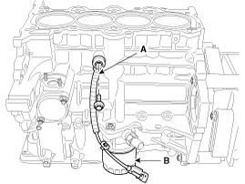
Remove the knock sensor (A) and the oil filter (B).
Remove the oil pressure switch. (Refer to Lubrication System - Oil Pressure Switch)
Remove the oil pan. (Refer to Lubrication System - "Oil Pan")
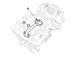
Remove the oil filter (A).
Remove the rear oil seal. (Refer to Cylinder Block - "Rear Oil Seal")
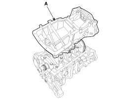
Remove the ladder frame (A).
Check the connecting rod side clearance.
Remove the connecting rod caps and inspect the oil clearance.
Remove the piston and connecting rod assembly.
Using a ridge reamer, remove all carbon from the upper part of the cylinder.
Push the piston, connecting rod assembly, and upper bearing out through the top of the cylinder block.
Keep the bearings, connecting rod, and cap together.
Arrange the piston and connecting rod assemblies in the correct order.
Remove the main bearing cap and check the oil clearance.
Check the crankshaft end play.
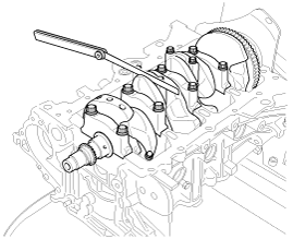
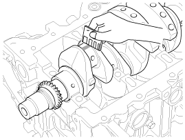
Lift the crankshaft (A) out of the engine, taking care not to damage the journals.
Arrange the main bearings and thrust bearings in the correct order.
Remove the piston cooling jet (A).
Check the fit between the piston and piston pin. Try moving the piston back and forth on the piston pin. If any movement is felt, replace the piston and pin as a set.
Remove the piston rings.
Using a piston ring expander, remove the 2 compression rings.
Remove the 2 side rails and the coil spring.
Arrange the piston rings only in the correct order.
Remove the connecting rod from the piston. Using a press, remove the piston pin from the piston. (Press-out load: 500–1500 kg (1102–3306 lb))
Inspection
Connecting Rod and Crankshaft
Inspect the connecting rod side clearance. Using a feeler gauge, measure the side clearance while moving the connecting rod back and forth. End of play. Standard: 0.10 ~ 0.25 mm (0.0039 ~ 0.0098 in.) Maximum: 0.35 mm (0.0138 in.)
If out of specification, install a new connecting rod.
If still out of specification, replace the crankshaft.
Check the connecting rod bearing oil clearance.
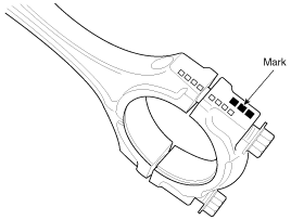
Make sure the alignment marks on the connecting rod and cap are aligned for correct reassembly.
Remove the 2 connecting rod cap bolts.
Remove the connecting rod cap and lower bearing.
Clean the crankshaft journal and bearing.
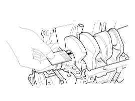
Place a piece of Plastigage on the crankshaft journal.
Install the lower bearing and cap, then tighten the bolts. Do not reuse the bolts. Tightening torque: 17.7 ~ 22 N·m + 88 ~ 92°
Do not rotate the crankshaft.
Remove the 2 bolts, connecting rod cap and lower bearing.
Measure the Plastigage at its widest point.
Standard oil clearance: 0.032 ~ 0.052 mm (0.0013 ~ 0.0020 in.)
If the Plastigage measurement is too wide or too narrow, remove the upper and lower bearings, then install new bearings with the same color code. Recheck the oil clearance.
Do not file, shim, or scratch the bearings or caps to adjust the clearance.
If Plastigage shows the clearance is still incorrect, try the next larger or smaller size bearing.
If the proper clearance cannot be obtained using the appropriate larger or smaller size bearings, replace the crankshaft and recheck.
If the markings are illegible due to dirt and dust buildup, do not scrape them off or use a wire brush. Clean them only with solvent or detergent.
Location of connecting rod mark Connecting Rod Journal Classification
Mark
Connecting Rod Big End Inside Diameter
A, 0
45.000 ~ 45.006 mm (1.7717 ~ 1.7719 in.)
B, 00
45.006 ~ 45.012 mm (1.7719 ~ 1.7721 in.)
C, 000
45.012 ~ 45.018 mm (1.7721 ~ 1.7724 in.)
Location of Crankshaft Pin Diameter Mark Crankshaft Pin Diameter Classification
Mark
Crankshaft Journal Outer Diameter
1
41.954 ~ 41.960 mm (1.6517 ~ 1.6520 in.)
2
41.966 ~ 41.960 mm (1.6522 ~ 1.6520 in.)
3
41.960 ~ 41.954 mm (1.6520 ~ 1.6517 in.)
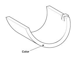
Location of Connecting Rod Bearing Color Connecting Rod Bearing Classification
Mark
Color
Connecting Rod Bearing Thickness
A
Blue
1.514 ~ 1.517 mm (0.0596 ~ 0.0597 in.)
B
Black
1.511 ~ 1.514 mm (0.0595 ~ 0.0596 in.)
C
None
1.508 ~ 1.511 mm (0.0594 ~ 0.0595 in.)
D
Green
1.505 ~ 1.508 mm (0.0593 ~ 0.0594 in.)
E
Red
1.502 ~ 1.505 mm (0.0591 ~ 0.0593 in.)
Select the bearing using the selection table. Connecting Rod Bearing Selection Table
Connecting Rod Mark
A, 0
B, 00
C, 000
Crankshaft Journal Mark
1
E (Red)
D (Green)
C (None)
2
D (Green)
C (None)
B (Black)
3
C (None)
B (Black)
A (Blue)
Inspect the connecting rods.
When reinstalling, make sure the cylinder numbers marked on the connecting rod and cap match those noted during disassembly. When installing a new connecting rod, make sure the bearing locking tabs are on the same side.
Replace the connecting rod if it is damaged on the rod surface at either end. Also, if the steps are worn or the surface is heavily roughened, the small end inside diameter is visible, and the rod must also be replaced.
Using a connecting rod aligner, check the connecting rod for bend and twist. If the measured value is close to the repair limit, correct the rod using a press. Replace any connecting rod that is severely bent or distorted. Allowable connecting rod bend: 0.05 mm/100 mm (0.0020 in./3.94 in.) or less. Allowable connecting rod twist: 0.10 mm/100 mm (0.0039 in./3.94 in.) or less.
When installing connecting rods without bearings, there must be no difference in the side surfaces.
Check the crankshaft bearing oil clearance.
To check the oil clearance between the main bearing and journal, remove the main bearing caps and lower bearings.
Clean each main journal and lower bearing with a clean shop towel.
Place one strip of Plastigage on each main journal.
Install the lower bearings and caps, then tighten the bolts.
Tightening torque: 17.7 ~ 22 N·m + 88 ~ 92°
Do not rotate the crankshaft.
Remove the cap, lower the bearing again, and measure the widest part of the Plastigage. Standard oil clearance: No. 1, 2, 3, 4, 5: 0.021 ~ 0.042 mm (0.0008 ~ 0.0017 in.)
If the Plastigage is too wide or too narrow, remove the upper and lower bearings, then install new bearings with the same color code. (Refer to the crankshaft main bearing selection table in this group.) Recheck the oil clearance.
Do not grind, shim, or scratch the bearings or cap to adjust the clearance.
If Plastigage shows the clearance is still incorrect, try the next larger or smaller bearing. (Refer to the crankshaft main bearing selection table in this group.) Recheck the oil clearance.
If the proper clearance cannot be obtained using bearings of larger or smaller size, replace the crankshaft and start over.
If the markings are illegible due to dirt and dust buildup, do not scrape them off or use a wire brush. Clean them only with solvent or detergent.
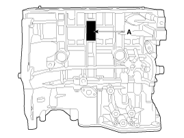
Location of Cylinder Block Crankshaft Bore Mark. Letters are stamped on the side of the block as a mark (A) for the size of each of the 5 main bore holes. Use them, along with the numbers or letters stamped on the crankshaft (main journal size marks), to select the correct bearings. Cylinder Block Crankshaft Bore Classification
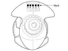
Location of the mark on the crankshaft main journal Crankshaft Main Journal Classification
Mark
Crankshaft Main Journal Outside Diameter
1
47.960 ~ 47.954 mm (1.8882 ~ 1.8879 in.)
2
47.954 ~ 47.948 mm (1.8879 ~ 1.8877 in.)
3
47.948 ~ 47.942 mm (1.8877 ~ 1.8875 in.)
Crankshaft Main Bearing Color Location Crankshaft Main Bearing Classification
Mark
Color
Thickness of the crankshaft main bearing
№1, 2, 3, 4, 5
A
Blue
2.026 ~ 2.029 mm (0.0798 ~ 0.0799 in.)
B
Black
2.023 ~ 2.026 mm (0.0796 ~ 0.0798 in.)
C
None
2.020 ~ 2.023 mm (0.0795 ~ 0.0796 in.)
D
Green
2.017 ~ 2.020 mm (0.0794 ~ 0.0795 in.)
E
Red
2.014 ~ 2.017 mm (0.0793 ~ 0.0794 in.)
Select the bearing using the selection table. Crankshaft Main Bearing Selection Table
Crankshaft Main Journal Bore Mark on Cylinder Block
A
B
C
Crankshaft main journal mark
1
E (Red)
D (Green)
C (None)
2
D (Green)
C (None)
B (Black)
3
C (None)
B (Black)
A (Blue)
Inspect the crankshaft end play. Using a dial indicator, measure the end play while moving the crankshaft back and forth with a screwdriver. End of play. Standard: 0.05 ~ 0.25 mm (0.0020 ~ 0.0098 in.) Limit: 0.30 mm (0.0118 in.) If the end play exceeds the maximum, replace the center main bearing.
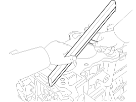
Remove the gasket material. Using a gasket scraper, remove all gasket material from the upper surface of the cylinder block.
Clean the cylinder block. Using a soft brush and solvent, thoroughly clean the cylinder block.
Inspect the cylinder block upper surface for flatness. Using a precision straightedge and feeler gauge, measure the surface contacting the cylinder head gasket for distortion. Cylinder block gasket surface flatness Standard: Overall less than 0.05 mm (0.0020 in.) Less than 0.02 mm (0.0008 in.) for a 100 mm (3.9370 in.) x 100 mm (3.9370 in.) section
Inspect the cylinder bore. Visually check the cylinder for vertical scratches. If deep scratches are present, replace the cylinder block.
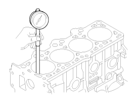
Check the cylinder bore diameter. Using a cylinder gauge, measure the cylinder bore diameter at the positions in both the axial and transverse directions.
Standard diameter: 77.00 ~ 77.03 mm (3.0315 ~ 3.0327 in.)
Check the cylinder bore size code on the side of the cylinder block. Cylinder Bore Size Classification
Mark
Cylinder Inner Diameter
A
77.00 ~ 77.01 mm (3.0315 ~ 3.0319 in.)
B
77.01 ~ 77.02 mm (3.0319 ~ 3.0323 in.)
C
77.02 ~ 77.03 mm (3.0323 ~ 3.0327 in.)
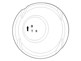
Check the piston size mark (A) on the piston top surface.A: Class T: Gasoline Engine (T-GDI) 6: 1.6 L Piston Outer Diameter Classification
Mark
Piston Outer Diameter
A
76.97 ~ 76.98 mm (3.0303 ~ 3.0307 in.)
B
76.98 ~ 76.99 mm (3.0307 ~ 3.0311 in.)
C
76.99 ~ 77.00 mm (3.0311 ~ 3.0315 in.)
Select a piston that matches the cylinder bore size class.
Piston-to-cylinder clearance: 0.02 - 0.04 mm (0.0008 - 0.0016 in.)
Clean the piston.
Using a gasket scraper, remove carbon deposits from the top of the piston.
Using a ring groove cleaner or a broken piston ring, clean the piston ring grooves.
Using solvent and a brush, thoroughly clean the piston.
Do not use a wire brush.
Measure the standard piston outer diameter at a point 12 mm (0.4724 in.) from the bottom of the piston.
Standard diameter: 76.97 ~ 77.00 mm (3.0303 ~ 3.0315 in.)
Cylinder Block Piston and Piston Rings
?
Test yourself
A quick Hyundai Sonata LF quiz: every answer comes with an explanation and a link to the manual page.