Engine Mechanical System
Cylinder Head Repair Procedures
In this manual: Engine Mechanical System
58steps
~363min
5/5difficulty
3special tools
Done 0 of 58
Removal
Engine removal is not necessary for this procedure.
|
|
- Remove the engine cover.
- Disconnect the negative battery cable.
- Remove the air duct and air cleaner assembly. (Refer to Intake and Exhaust System - "Air Cleaner")
- Disconnect the mounting bracket, then remove the battery. (Refer to Engine Electrical System - "Battery")
- Disconnect the ECM connector, then remove the battery tray. (Refer to Engine Electrical System - Battery)
- Remove the battery tray. (Refer to Engine Electrical System - "Battery")
- Remove the engine room cover.
- Loosen the drain plug and drain the engine coolant. Open the radiator cap to drain the coolant quickly. (Refer to Cooling System - "Engine Coolant")
- Remove the upper radiator hose and the lower hose. (Refer to Cooling System - "Radiator Hose").
- Disconnect the intake and exhaust hoses of the intercooler. (Refer to Intake and Exhaust System - "Intercooler Pipe and Hose")
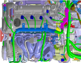
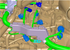
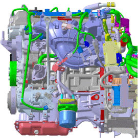
- Disconnect the engine wiring connector and the cable clip, then remove the cylinder head protector and the wiring from the engine.
- Disconnect the brake booster vacuum hose (A).
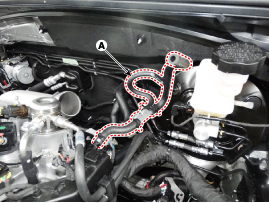
- Remove the heater hose (A).
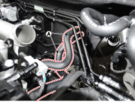
- Remove the vacuum hose assembly (A).

- Remove the cylinder head cover. (Refer to Cylinder Head Assembly - Cylinder Head Cover)
- Remove the timing chain cover. (Refer to Valve Timing - Timing Chain Cover)
- Remove the timing chain. (Refer to Valve Timing System - Timing Chain)
- Remove the camshaft. (Refer to Cylinder Head Assembly - "Camshaft")
- Remove the intake manifold. (Refer to Intake and Exhaust Systems — Intake Manifold)
- Remove the turbo exhaust manifold. (See Intake and Exhaust System - "Exhaust Manifold")
- Remove the delivery pipe assembly. (See Fuel System - "Delivery Pipe")
- Disconnect the bypass hose, then remove the water temperature control assembly. (Refer to Cooling System - "Water Temperature Control Assembly")
- Remove the heater pipe. (Refer to Cooling System - "Water Pipe")
- Remove the intake OCV (oil control valve). (See Fuel System - "CVVT Oil Control Valve")
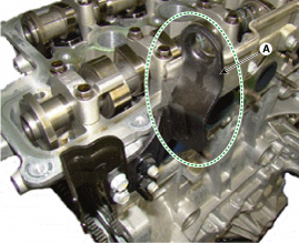
- Remove the rear suspension (A).
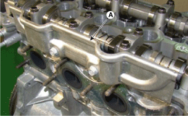
- Remove the cylinder head cover heat insulator (A).
- Remove the cylinder head bolts, then remove the cylinder head.
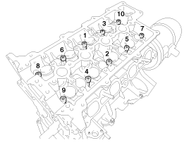
- Evenly loosen and remove the 10 cylinder head bolts in several passes, in the sequence shown.

Cylinder head distortion or cracking may result if the bolts are loosened in the wrong order.
- Remove the cylinder head from the cylinder block and place the cylinder head on wooden blocks.
Be careful not to damage the contact surfaces of the cylinder head and cylinder block.
- Evenly loosen and remove the 10 cylinder head bolts in several passes, in the sequence shown.
Disassembly
|
- Remove the MLA (A).
When removing the MLA, mark all MLAs so that they can be reinstalled in their original positions.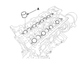
- Remove the valves.
- Using SST (09222-3K000, 09222-3K100), compress the valve spring and remove the valve cotter (keeper).
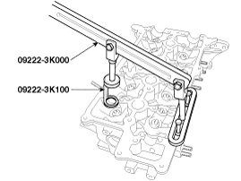
- Remove the spring retainer.
- Remove the spring retainer.
- Remove the valve.
- Remove the valve stem seal.
- Using a magnetic pick-up tool, remove the spring seat.
Do not reuse the valve stem oil seals.
- Using SST (09222-3K000, 09222-3K100), compress the valve spring and remove the valve cotter (keeper).
Inspection
Cylinder head cover
- Inspect for flatness. Using a precision straightedge and a feeler gauge, measure the surfaces contacting the cylinder block and manifolds for warpage. Cylinder head gasket surface flatness Standard: Overall less than 0.05 mm (0.0020 in.); less than 0.02 mm (0.0008 in.) per 100 mm (3.9370 in.) x 100 mm (3.9370 in.) section
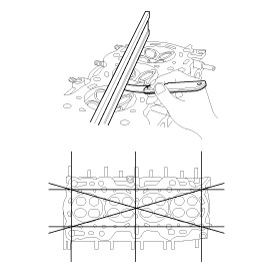
- Inspect for cracks. Check the combustion chamber, intake ports, exhaust ports and the cylinder head surface for cracks. If any cracks are found, replace the cylinder head.
- Inspect the valve stems and valve guides.
- Using a caliper gauge, measure the inside diameter of the valve guide.
Valve guide inside diameter: 5.500 - 5.512 mm (0.2165 - 0.2170 in.)
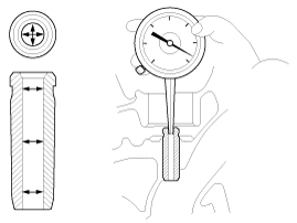
- Using a micrometer, measure the outer diameter of the valve stem. Valve Stem Outer Diameter Intake: 5.465 ~ 5.480 mm (0.2152 ~ 0.2157 in.) Exhaust: 5.458 ~ 5.470 mm (0.2149 ~ 0.2154 in.)
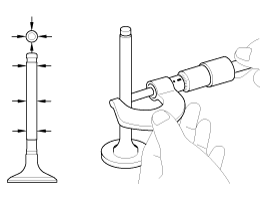
- Subtract the valve stem outside diameter measurement from the valve guide inside diameter measurement. Valve stem-to-guide clearance Intake: 0.020 ~ 0.047 mm (0.0008 ~ 0.0019 in.) Exhaust: 0.030 ~ 0.054 mm (0.0012 ~ 0.0021 in.) If the clearance is greater than specified, replace the valve or the cylinder head.
- Using a caliper gauge, measure the inside diameter of the valve guide.
Valve guide inside diameter: 5.500 - 5.512 mm (0.2165 - 0.2170 in.)
- Inspect the valves.
- Make sure the valve face is ground to the correct valve face angle.
- Check the valve face for wear. If the valve face is worn, replace the valve.
- Check the valve head margin thickness. If the margin thickness is less than the minimum, replace the valve.
Standard margin thickness — Intake: 1.10 mm (0.0433 in.) Exhaust: 1.26 mm (0.0496 in.)

- Check the valve length. Standard valve length Intake: 93.15 mm (3.6673 in.) Exhaust: 92.60 mm (3.6457 in.)
- Check the valve stem tip for wear. If the valve stem tip is worn, replace the valve.
- Inspect the valve seats.
- Check the valve seat for signs of overheating and improper contact with the valve face. If the valve seat is worn, replace the cylinder head.
- Inspect the valve guide for wear. If the valve guide is worn, replace the cylinder head.
- Inspect the valve springs.
- Using a steel square, measure the valve spring squareness.
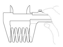
- Using a caliper gauge, measure the free length of the valve spring. Valve spring Standard free height: 45.1 mm (1.7756 in.) Out-of-square: less than 1.5°
Installation
|
- Install the valves.
- Install the spring seats.
- Using SST (09222-2B100), install a new valve stem seal.

- Do not reuse old valve stem seals.
- Improper seal installation may cause oil to leak past the valve guides.
The intake valve stem oil seals are different from the exhaust valve stem oil seals. Do not install them in the wrong positions. - Install the valve, valve spring and spring retainer, after applying engine oil to the end of each valve.
When installing the valve springs, the painted side must face the spring retainer.
- Using SST (09222-3K000, 09222-3K100), compress the spring and install the retainer locks. After installing the valves, make sure the retainer locks are properly seated before releasing the valve spring compression.
When installing the SST, use a torque of no more than 1.2 kgf·m. - Lightly tap the end of each valve stem two or three times with a wooden hammer handle to ensure proper seating of the valve and cotter.
- Install the MLA (mechanical lash adjuster). Make sure the MLA (A) rotates smoothly by hand.
All MLAs must be installed in their original positions.
Installation
|
- Install the cylinder head assembly.
- Before installation, remove hardened sealant from the cylinder block and cylinder head surfaces.
- Before installing the cylinder head gasket, apply sealant to the top surface of the cylinder block and install the gasket within five minutes.

Width: 2.0 ~ 3.0 mm (0.0787 ~ 0.1181 in.) Position: 1.0 ~ 1.5 mm (0.0394 ~ 0.0591 in.) Specified sealant: TB 1217H or LOCTITE 5900H
See illustration for sealant application.
- After installing the cylinder head gasket on the cylinder block, apply sealant to the top surface of the cylinder head gasket and assemble within five minutes.
- Carefully install the cylinder head so as not to damage the gasket.
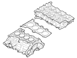
- Install the cylinder head bolts with washers.
- Tighten the 10 cylinder head bolts in several passes in the specified sequence.
Tightening torque: 29 N·m + 90° + 90°
Always use new cylinder head bolts.
- Tighten the 10 cylinder head bolts in several passes in the specified sequence.
- Install the cylinder head cover heat shield (A).
Tightening torque: 9.8 ~ 11.8 N·m
- Install the rear suspension (A).
- Install the oil control valve (OCV). (Refer to Fuel System - "CVVT Oil Control Valve (OCV)").
- Install the heater hose. (Refer to Cooling System - "Water Hose")
- Install the humidity control unit and bypass hose. (Refer to Cooling System - "Water Control Assembly")
- Install the delivery pipe assembly. (Refer to Fuel System - "Delivery Pipe")
- Install the intake manifold. (Refer to Air Intake and Exhaust System - "Intake Manifold").
- Install the turbo manifold. (Refer to Intake and Exhaust System - "Exhaust Manifold")
- Install the camshaft. (Refer to Cylinder Head Assembly - "Camshaft")
- Install the timing chain. (Refer to Timing System - Timing Chain)
- Install the timing chain cover. (Refer to Timing System - "Timing Chain Cover")
- Install the cylinder head cover. (Refer to Cylinder Head Assembly - "Cylinder Head Cover")
Do not reuse the removed gasket. - Install the vacuum hose assembly (A).
Tightening torque: 9.8 ~ 11.8 N·m
- Connect the heater hose (A).
- Connect the vacuum brake hose (A).
- Install in the reverse order of removal.
|
Test yourself
A quick Hyundai Sonata LF quiz: every answer comes with an explanation and a link to the manual page.
Was this page helpful?