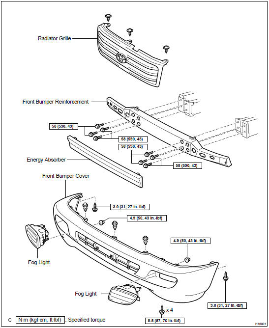
Front bumper
COMPONENTS
ADJUSTMENT
1. ADJUST DOOR IN FORWARD/BACKWARD AND VERTICAL DIRECTIONS
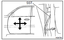
Using SST, loosen the body side hinge bolts to adjust.
SST 09812-00010
Torque: 23 N·m
2. ADJUST DOOR IN RIGHT/LEFT AND VERTICAL DIRECTIONS
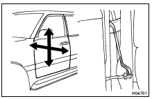
Loosen the door side hinge bolts to adjust.
HINT: Substitute the bolt with washer for the centering bolt ( BO-6 ).
Torque: 26 N·m
3. ADJUST DOOR LOCK STRIKER

(b) Loosen the striker mounting screws.
Torque: 11 N·m
(c) Using a plastic hammer, tap the striker to adjust it.
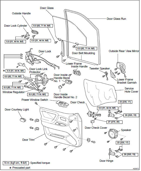
COMPONENTS
Disassembly
1. REMOVE LOWER FRAME BRACKET GARNISH
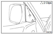
Using a screwdriver, remove the lower frame bracket garnish.
HINT: Tape up the screwdriver tip before use.
2. REMOVE POWER WINDOW SWITCH
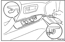
(a) Using a screwdriver, remove the power window switch as shown in the illustration.
HINT: Tape up the screwdriver tip before use.
(b) Disconnect the connector.
3. REMOVE DOOR INSIDE HANDLE BEZEL No. 2
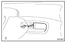
Using a screwdriver, remove the door inside handle bezel No.
2 as shown in the illustration.
HINT: Tape up the screwdriver tip before use.
4. REMOVE DOOR INSIDE HANDLE BEZEL No. 1
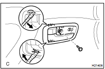
(b) Using a screwdriver, remove the door inside handle bezel No. 1 as shown in the illustration.
HINT: Tape up the screwdriver tip before use.
5. REMOVE DOOR COURTESY LIGHT
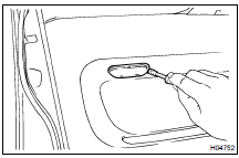
Using a screwdriver, remove the door courtesy light, then disconnect the connector.
HINT: Tape up the screwdriver tip before use.
6. REMOVE DOOR TRIM
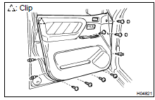
(c) Insert a screwdriver between the door and the door trim to pry the trim.
NOTICE: Be careful not to damage the door and the door trim.
HINT: Tape up the screwdriver tip before use.
(d) Pull the trim upward to remove it.
7. REMOVE INSIDE HANDLE
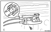
(b) Disconnect the 2 control cables from the inside handle as shown in the illustration.
8. REMOVE TWEETER SPEAKER
Disconnect the connector, then remove the bolt and the tweeter speaker.
9. REMOVE OUTSIDE REAR VIEW MIRROR
Disconnect the connector, then remove the 3 bolts and the outside rear view mirror.
10. REMOVE SERVICE HOLE COVER
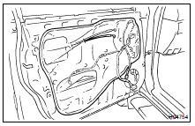
(b) Remove the service hole cover.
NOTICE: Do not tear the cover.
HINT: At the time of reassembly, pull out the 2 control cables and wire harness through the service hole cover.
11. REMOVE DOOR BELT MOULDING
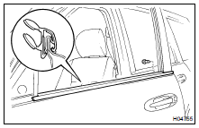
(b) Using a scraper, remove the door belt moulding.
HINT: Tape up the scraper tip before use.
12. REMOVE DOOR GLASS
(a) Open the door glass until the bolts appear in the service hole.(b) Remove the 2 bolts and the door glass.
Torque: 8 N·m
NOTICE: Do not damage the door glass.
HINT: Pull the glass upward to remove it.
13. REMOVE SPEAKER
Remove the 3 screws and the speaker, then disconnect the connector.
14. REMOVE DOOR GLASS RUN
15. REMOVE LOWER FRAME
Remove the bolt and the lower frame.
16. REMOVE WINDOW REGULATOR
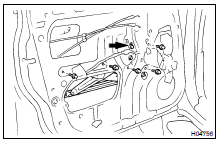
(a) Disconnect the connector, then remove the 5 bolts.
Torque: 8 N·m
(b) Loosen the bolt and the window regulator.
Torque: 8 N·m
HINT:
- Remove the regulator through the service hole.
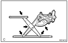
- At the time of reassembly, apply MP grease to the window regulator.
NOTICE: At the time of reassembly, do not apply grease to the spring of the window regulator.
17. REMOVE DOOR LOCK
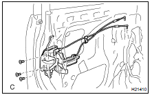
(d) Using a torx wrench, remove the 3 screws and the door lock through the service hole.
Torx wrench: T30 (Part No. 09042-00010 or locally manufactured tool)
Torque: 5 N·m
HINT: At the time of reassembly:
- Apply adhesive to the 3 screws.
Part No. 08833-00070, THREE BOND 1324 or equivalent.

- Remove the protector, and apply MP grease to the sliding and rotating parts of the door lock.
18. REMOVE OUTSIDE HANDLE WITH DOOR LOCK CYLINDER
(a) Remove the 2 bolts and the outside handle with the door lock cylinder.
Torque: 5 N·m
(b) Remove the bolt and the door lock cylinder from the outside handle.
Torque: 5 N·m
REASSEMBLY
Reassembly is in the reverse order of disassembly
Test yourself
A quick Toyota Land Cruiser quiz: every answer comes with an explanation and a link to the manual page.