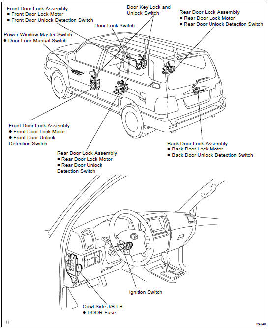
Location
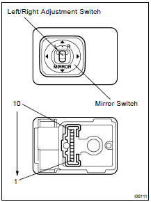
INSPECTION
1. INSPECT LEFT SIDE MIRROR SWITCH CONTINUITY

2. INSPECT RIGHT SIDE MIRROR SWITCH CONTINUITY
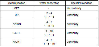
3. INSPECT RETRACT SWITCH CONTINUITY
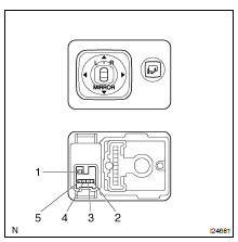
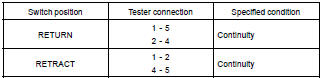
If continuity is not as specified, replace the switch
4. INSPECT MIRROR SWITCH CIRCUIT
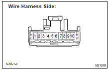
Disconnect the connector from the switch and inspect the connector on the wire harness side.

If the circuit is not as specified, inspect the circuits connected to other parts.
5. INSPECT INDICATOR LIGHT OPERATION
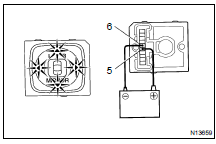
Connect the positive (+) lead from the battery to terminal 5 and the negative (-) lead to terminal 6, and check that the indicator light does not light up, replace the switch.
6. INSPECT MIRROR MOTOR OPERATION

(a) Connect the positive (+) lead from the battery to terminal 8 and the negative (-) lead to terminal 7, and check that the mirror turns to the left side.
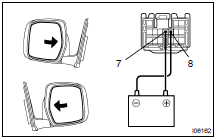
(b) Reverse the polarity, and check that the mirror turns to the right side.
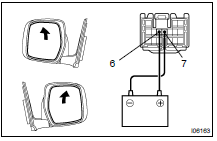
(c) Connect the positive (+) lead from the battery to terminal 6 and the negative (-) lead to terminal 7, and check that the mirror turns upward.
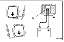
(d) Reverse the polarity, and check that the mirror turns downward.
If operation is not as specified, replace the mirror assembly.
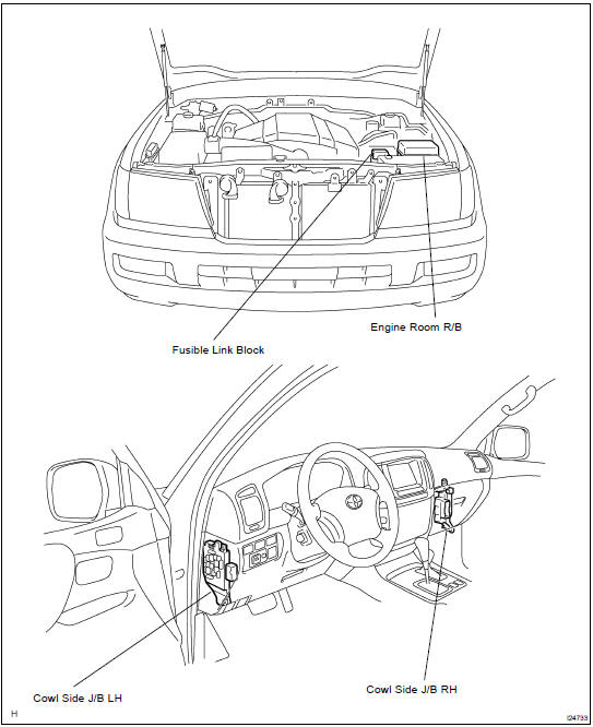
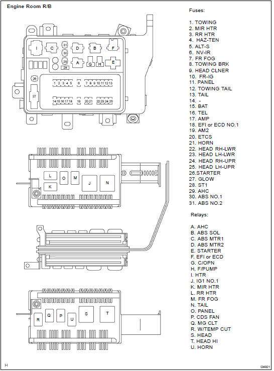
LOCATION
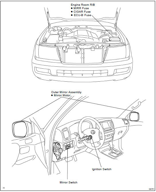
INSPECTION
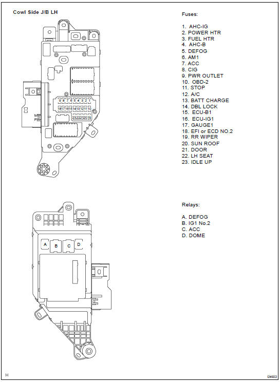
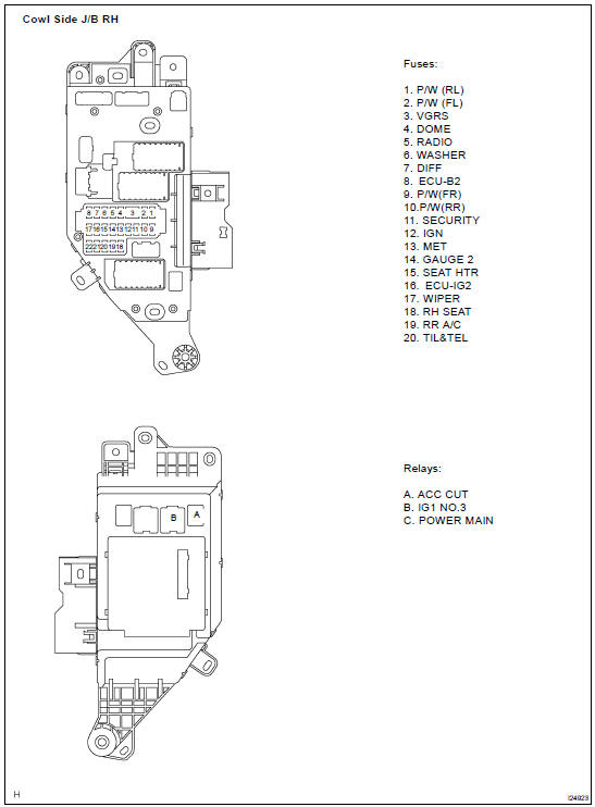
1. INSPECT ENGINE ROOM R/B CIRCUIT

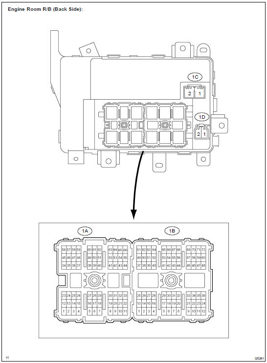
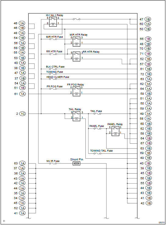

(a) Remove the fuse from the junction block and inspect the connector on junction block side.
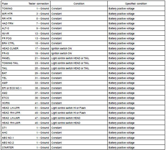
If the circuit is not as specified, inspect the circuits connected to other parts.
(b) Remove the relay from the junction block and inspect the connector on junction block side.
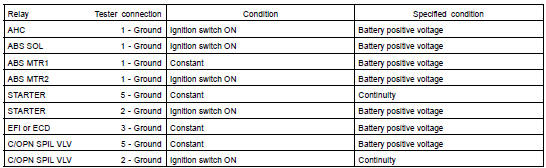
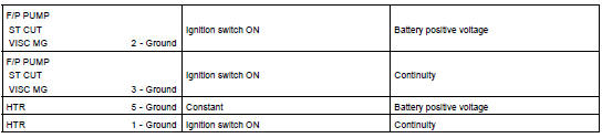
If the circuit is not as specified, inspect the circuits connected to other parts.
(c) Inspect Engine Room Junction Block Inner Cercuit: Inspect the connector on junction block side.
HINT: Remove the junction block from the vehicle.
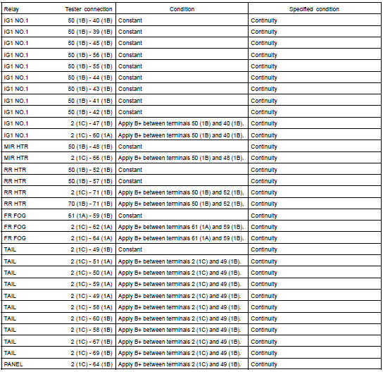
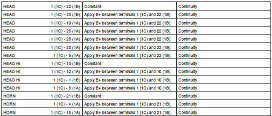
If the circuit is not as specified, replace it with junction block assembly.
HINT: The relay is built in engine room junction block. Also the relay is constructed with a relay block that is in the junction block as a unit. To disconnect the wire harness connecting with relay block is impossible. If the relay has a malfunction, replace it with junction block assembly wire harness together.
2. INSPECT COWL SIDE J/B LH CIRCUIT
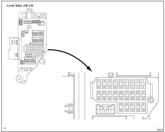
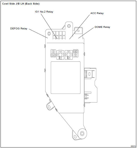
(a) Remove the fuse from the junction block and inspect the connector on junction block side.
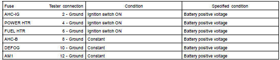
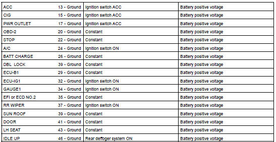
If the circuit is not as specified, inspect the circuits connected to other parts.
(b) Remove the relay from the junction block and inspect the connector on junction block side.
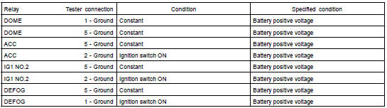
If the circuit is not as specified, inspect the circuits connected to other parts.
3. INSPECT COWL SIDE J/B RH CIRCUIT

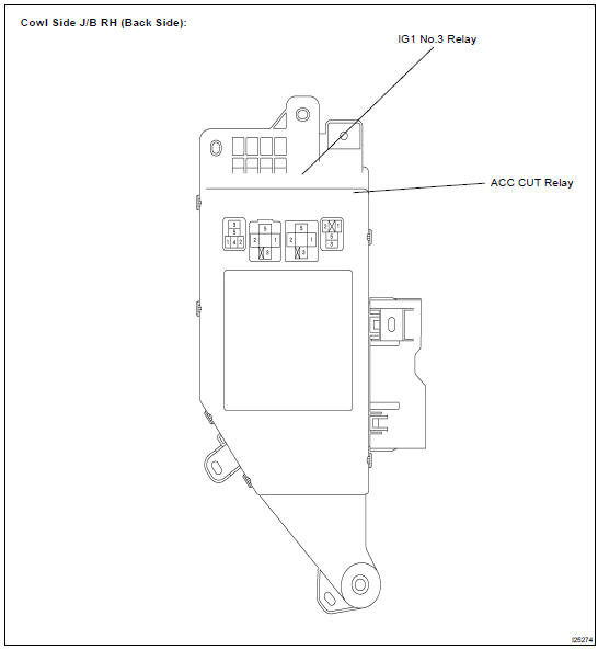
(a) Remove the fuse from the junction block and inspect the connector on junction block side.
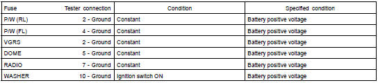
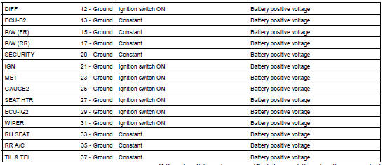
If the circuit is not as specified, inspect the circuits connected to other parts.
Remove the relay from the junction block and inspect the connector on junction block side.

If the circuit is not as specified, inspect the circuits connected to other parts.
LOCATION
INSPECTION
1. INSPECT POWER QUARTER WINDOW SWITCH CONTINUITY
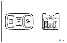
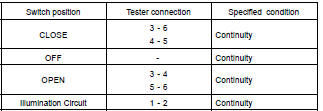
If continuity is not as specified, replace the switch.
2. Left side: INSPECT POWER VENT WINDOW MOTOR OPERATION

(a) Connect the positive (+) lead from the battery to terminal 1 and the negative (-) lead to terminal 2, and check that the window link moves to OPEN position.
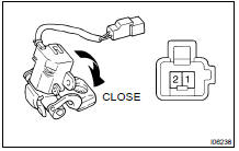
(b) Remove the polarity and check that the window link moves to CLOSE position.
If operation is not as specified, replace the window motor.
3. Right side: INSPECT POWER VENT WINDOW MOTOR OPERATION
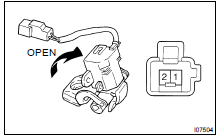
(a) Connect the positive (+) lead from the battery to terminal 2 and the negative (-) lead to terminal 1, and check that the window link moves to OPEN position.
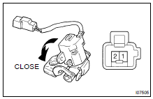
(b) Remove the polarity and check that the window link moves to CLOSE position.
LOCATION
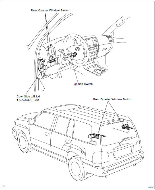
INSPECTION
1. INSPECT POWER QUARTER WINDOW SWITCH CONTINUITY
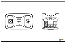

If continuity is not as specified, replace the switch.
2. Left side: INSPECT POWER VENT WINDOW MOTOR OPERATION
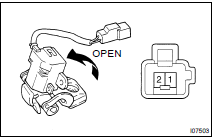
(a) Connect the positive (+) lead from the battery to terminal 1 and the negative (-) lead to terminal 2, and check that the window link moves to OPEN position.
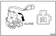
(b) Remove the polarity and check that the window link moves to CLOSE position.
If operation is not as specified, replace the window motor.
3. Right side: INSPECT POWER VENT WINDOW MOTOR OPERATION

(a) Connect the positive (+) lead from the battery to terminal 2 and the negative (-) lead to terminal 1, and check that the window link moves to OPEN position.
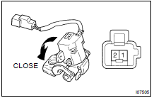
(b) Remove the polarity and check that the window link moves to CLOSE position
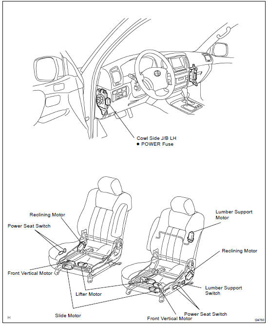
LOCATION
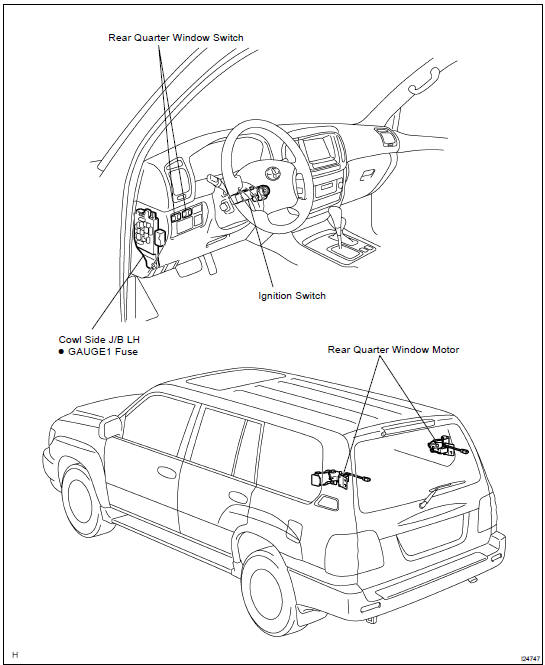
INSPECTION
1. INSPECT DRIVER'S POWER SEAT SWITCH CONTINUITY
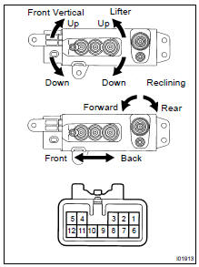
Slide Switch:
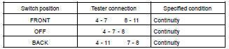
Front vertical switch:

Lifter switch:

Reclining switch:

If continuity is not as specified, replace the switch.
2. INSPECT DRIVER'S POWER SEAT SWITCH CIRCUIT
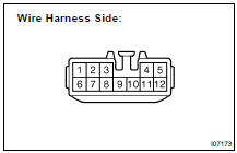
(b) Inspect the connector on the wire harness side.

If circuit is not as specified, inspect the circuits connected to other parts.
3. INSPECT PASSENGER'S POWER SEAT SWITCH CONTINUITY
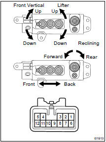
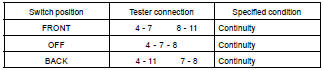
Slide switch:
Front vertical switch:
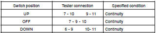
Lifter switch:
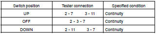
Reclining switch:
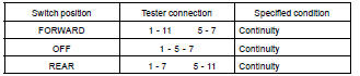
If continuity is not as specified, replace the switch.
4. INSPECT PASSENGER'S POWER SEAT SWITCH CIRCUIT
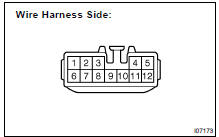
(b) Inspect the connector on the wire harness side.

If circuit is not as specified, inspect the circuits connected to other parts.
5. INSPECT DRIVER'S LUMBAR SUPPORT SWITCH CONTINUITY
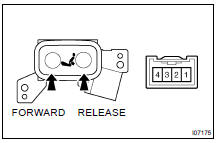
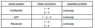
If continuity is not as specified, replace the switch.
6. INSPECT DRIVER'S LUMBAR SUPPORT SWITCH CIRCUIT

(b) Inspect the connector on the wire harness side.

If circuit is not as specified, inspect the circuits connected to other parts.
7. INSPECT SLIDE MOTOR OPERATION

(b) Reverse the polarity, check that the motor turns counterclockwise.
If operation is not as specified, replace the seat adjuster.
8. INSPECT SLIDE MOTOR PTC THERMISTOR OPERATION
( ): Passenger side
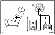
(b) Continue to apply voltage, check that current changes to less than 1 ampere within 4 to 90 seconds.
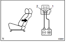
(d) Approximately 60 seconds later, connect the positive (+) lead from the battery to terminal 1 (2) and the negative (-) lead to terminal 2 (1), check that the seat cushion begins to move backwards.
If operation is not as specified, replace the seat adjuster.
9. INSPECT FRONT VERTICAL MOTOR OPERATION
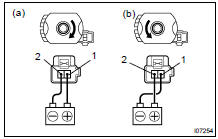
(b) Reverse the polarity, check that the motor turns counterclockwise.
If operation is not as specified, replace the seat adjuster.
10. INSPECT FRONT VERTICAL MOTOR PTC THERMISTOR OPERATION
( ): Passenger side
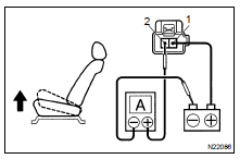
(b) Continue to apply voltage, check that the current changes to less than 1 ampere within 4 to 90 seconds.
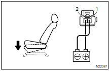
(d) Approximately 60 seconds later, connect the positive (+) lead from the battery to terminal 2 (1) and the negative (-) lead to terminal 1 (2), check that the seat cushion begins to descend.
If operation is not as specified, replace the seat adjuster.
11. INSPECT LIFTER MOTOR OPERATION

(b) Reverse the polarity, check that the motor turns counterclockwise.
If operation is not as specified, replace the seat adjuster.
12. INSPECT LIFTER MOTOR PTC THERMISTOR OPERATION
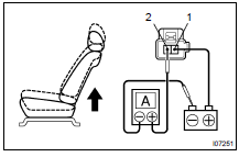
(b) Continue to apply voltage, check that the current changes to less than 1 ampere within 4 to 90 seconds.

(d) Approximately 60 seconds later, connect the positive (+) lead from the battery to terminal 2 (1) and the negative (-) lead to terminal 1 (2), check that the seat cushion begins to descend.
If operation is not as specified, replace the seat adjuster
13. INSPECT RECLINING MOTOR OPERATION

(b) Reverse the polarity, check that the motor turns counterclockwise.
If operation is not as specified, replace the seat adjuster.
14. INSPECT RECLINING MOTOR PTC THERMISTOR OPERATION
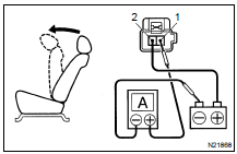
(b) Continue to apply voltage, check that the current changes to less than 1 ampere within 4 to 90 seconds.
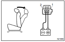
(d) Approximately 60 seconds later, connect the positive (+) lead from the battery to terminal 1 and the negative (-) lead to terminal 2, check that the seat back begins to fall backward.
If operation is not as specified, replace the seat adjuster
15. INSPECT LUMBAR SUPPORT MOTOR OPERATION
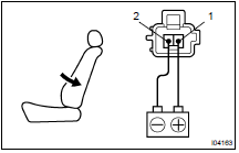
(a) Connect the positive (+) lead from the battery to terminal 1 and the negative (-) lead to terminal 2, check that the lumbar support moves to release side.
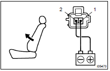
(b) Reverse the polarity, check that the lumbar support moves forward.
If operation is not as specified, replace the seat adjuster.
16. INSPECT LUMBAR SUPPORT MOTOR CIRCUIT BREAKER OPERATION
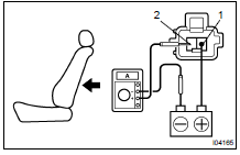
(a) Connect the positive (+) lead from the battery to terminal 2 and the negative (-) lead to terminal 1 on the lumbar support motor connector and move the lumbar support to front end position.
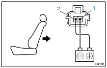
(c) Reverse the polarity, check that the lumbar support begins to move to release side within approximately 60 seconds.
If operation is not as specified, replace the motor.
LOCATION
Test yourself
A quick Toyota Land Cruiser quiz: every answer comes with an explanation and a link to the manual page.