Installation
1. INSTALL REINFORCEMENT
2. INSTALL NO. 1 BRACE
3. INSTALL FLOOR BRACE
4. INSTALL GLOVE COMPARTMENT DOOR DAMPER
5. INSTALL NO. 4 HEATER TO REGISTER DUCT
6. INSTALL NO. 3 HEATER TO REGISTER DUCT
7. INSTALL ECM ( SF-60 )
8. INSTALL INSTRUMENT PANEL
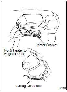
HINT:
- Install the airbag connector between the No. 5 heater to register duct and the center bracket temporarily, then install the instrument panel.
- Remove the airbag connector before installing the lower No. 2 panel.
(b) Install the 2 bolts to the front passenger airbag assembly.
Torque: 20 N·m
(c) Connect the junction connectors.
HINT: The connectors can be connected by tightening the bolts
9. INSTALL FRONT CONSOLE BOX AND FRONT CONSOLE BOX BRACKET

Install the front console box and the front console box bracket with the 2 bolts.
10. INSTALL CENTER LOWER CLUSTER FINISH PANEL

Connect the connector, then install the center lower cluster finish panel.
11. INSTALL REAR CONSOLE BOX

(a) w/o Disc player changer: Install the rear console box with the 6 bolts and the 8 screws.
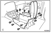
(b) w/ Disc player changer: Install the rear console box with the 4 bolts and the 8 screws.
12. INSTALL REAR RADIO CONTROL PANEL
Install the rear radio control panel with the 3 screws, then connect the connector
13. INSTALL CONSOLE REAR END PANEL
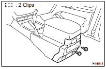
(b) Install the rear console cup holder box.
14. INSTALL FRONT CONSOLE PANEL
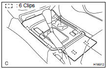
Install the front console panel, then install the transfer shift lever knob.
15. INSTALL RADIO WITH A/C CONTROL ASSEMBLY
HINT: w/ Navigation System: When removing/installing or replacing EMV, or when disconnecting/ connecting the battery terminal, turn the IG ON and OFF twice for initial display setting.
16. INSTALL CENTER REGISTERS
Connect the connectors, then install the center registers.
17. INSTALL LOWER NO. 2 PANEL
Install the lower No. 2 panel with the 3 screws.
18. CONNECT AIRBAG CONNECTOR ( RS-41 )
19. INSTALL GLOVE COMPARTMENT DOOR
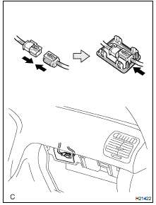
(b) Install the 2 screws.
20. INSTALL COMBINATION METER
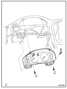
(c) Install the combination meter by tightening the screws, "A", "B" and "C" in order.
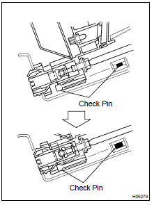
(d) Tighten the connection bolts.
HINT:
- When connection completes, the bolts turns idly, causing turning noise.
- Check that the connection check pins protrude from the lower side of the connection bolts.
NOTICE: Follow the procedures in the order of (c) and (d). Otherwise, set-in connectors on the wire harness side and connectors on the meter side might not be connected properly.
21. INSTALL STEERING COLUMN ( SR-24 or SR-37 )
22. INSTALL NO. 2 HEATER TO REGISTER DUCT
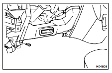
Install the No. 2 heater to register duct with the screw.
23. INSTALL COMBINATION SWITCH
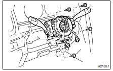
(b) Install the clamp, then connect the connectors.
24. INSTALL COLUMN COVERS
Install the column covers with the 3 screws.
25. INSTALL LH LOWER PANEL
Install the LH lower panel with the 3 bolts.
26. INSTALL LOWER NO. 1 PANEL
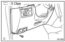
Connect the connector, then install the lower No. 1 panel with the screw.
27. INSTALL HOOD LOCK CONTROL CABLE LEVER AND FUEL LID CONTROL CABLE LEVER
(a) Install the fuel lid control cable lever with the 2 screws.(b) Install the hood lock control cable lever with the 2 screws
28. INSTALL CLUSTER FINISH PANEL
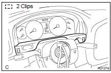
Connect the connecter, then install the cluster finish panel.
29. INSTALL STEERING WHEEL ( SR-24 or SR-37 )
30. INSTALL FRONT PILLAR GARNISH

(b) Use the same manner described above to the other side.
31. INSTALL FRONT ASSIST GRIP
(a) Install the assist grip with the 2 screws, then install the 2 assist grip plugs.(b) Use the same manner described above to the other side.
32. INSTALL FRONT DOOR OPENING TRIMS
33. INSTALL COWL SIDE TRIMS
34. INSTALL FRONT DOOR SCUFF PLATES
REASSEMBLY
Reassembly is in the reverse order of disassembly
Test yourself
A quick Toyota Land Cruiser quiz: every answer comes with an explanation and a link to the manual page.