Suspension
Front suspension lower no. 1 Arm
In this manual: Suspension
44steps
~274min
5/5difficulty
2special tools
Done 0 of 44
Components
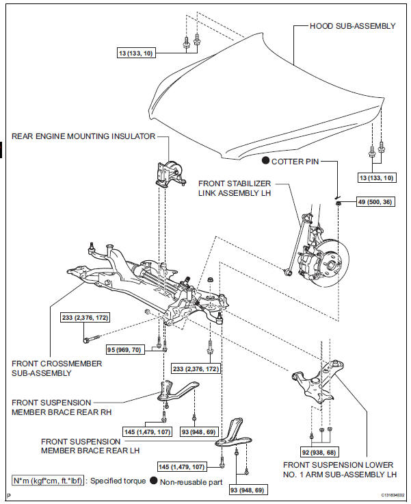
Removal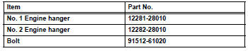
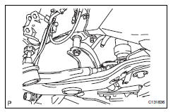
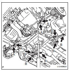
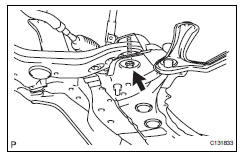
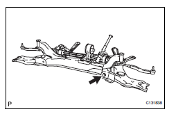
Hint: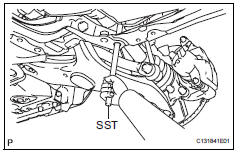
Removal
- Remove front wheel
- Remove hood sub-assembly
- Remove the hood (see page ed-4).
- Suspend engine assembly
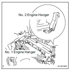
- Install the no. 1 And no. 2 Engine hangers with the bolts as shown in the illustration.
- Attach the sling device and the engine with the chain block.
- Disconnect front stabilizer link assembly lh (see page sp-30)
- Disconnect front stabilizer link assembly rh

- Use the same procedure described for the lh side.
- Disconnect front suspension lower no. 1 Arm sub-assembly lh

- Remove the 2 nuts and bolt, and disconnect the lower arm from the ball joint.
- Disconnect front suspension lower no. 1 Arm sub-assembly rh
Use the same procedures described for the lh side.
- Disconnect front crossmember subassembly
- Remove the 2 nuts, 2 bolts and engine mounting insulator rear.
- Remove the bolt from the suspension member.
- Support the crossmember with the jack.
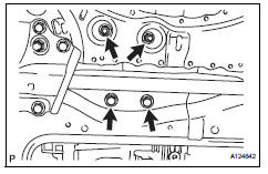
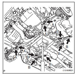
- Remove the bolts labeled a.
- Remove the 4 bolts from the member reinforcement.
- Remove the bolts labeled b.
- Remove the 6 bolts from the member brace.
- Slowly lower the jack, and disconnect the crossmember from the vehicle.
- Remove front suspension lower no. 1 Arm sub-assembly lh

- Remove the bolt and nut from the suspension member (front side).
- Remove the bolt and nut from the suspension member (rear side). Then remove the lower arm.
- Remove front suspension lower no. 1 Arm sub-assembly rh
Use the same procedures described for the lh side.
Installation- Temporarily install front suspension lower no. 1 Arm lh
- Temporarily install the lower arm with the bolt and nut to the front side.
- Temporarily install the lower arm with the bolt and nut to the rear side.
- Temporarily install front suspension no. 1 Lower arm sub-assembly rh
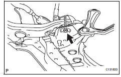
Hint:
Use the same procedures described for the lh side.
- Connect front crossmember subassembly
- Slowly raise the crossmember jack, and connect the crossmember to the body.
- Using sst, align the holes of the suspension member and body.
- Perform the procedure above on the other side.
- Install the member reinforcement with the 4 bolts labeled a.
- Install the suspension member brace with the 6 bolts labeled b.
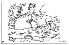
- Install the suspension member with the bolt to the body.
- Perform the procedure above on the other side.
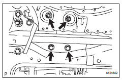
- Install the engine mounting insulator rear with the 2 nuts and 2 bolts.
- Install front stabilizer link assembly lh (see page sp-30)
- Connect front suspension lower no. 1 Arm sub-assembly lh
- Connect the lower arm with the 2 bolts and nut to the ball joint.
- Install front wheel
- Stabilize suspension (see page sp-12)
- Tighten front cross member sub-assembly
- Tighten the bolts and nuts.
- Tighten front suspension lower no. 1 Arm sub-assembly lh
- Using sst, and tighten the bolt on the front side.
Do not tighten the nut.
- Fix the nut in place and tighten the bolt on the rear side.
Do not tighten the nut.
- Tighten front suspension lower no. 1 Arm sub-assembly rh
Use the same procedures described for the lh side.
- Install hood sub-assembly (see page ed-7)
- Inspect and adjust hood sub-assembly
- Inspect and adjust the hood (see page ed-5).
- Inspect and adjust front wheel alignment
- Inspect and adjust the front wheel alignment (see page sp-3).
Test yourself
A quick Toyota RAV4 quiz: every answer comes with an explanation and a link to the manual page.
Was this page helpful?