Lighting
Ignition Switch Circuit
In this manual: Lighting
3steps
~18min
2/5difficulty
Done 0 of 3
DESCRIPTION
The Multiplex network body ECU receives the ACC and IG signals from the ignition switch.
WIRING DIAGRAM
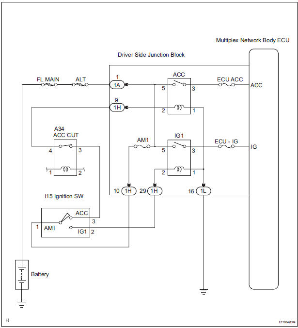
INSPECTION PROCEDURE
1 READ VALUE OF INTELLIGENT TESTER
- Connect the intelligent tester to DLC3.
- Turn the ignition switch ON and push the intelligent tester main switch ON.
- Select the items below in the DATA LIST, and read the displays on the intelligent tester.
BODY NO.1:

2 INSPECT FUSE
- Inspect the ECU ACC fuse, ECU-IG fuse and AM1 fuse in instrument panel junction block assembly.
3 INSPECT RELAY
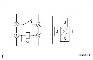
- Inspect ACC relay continuity.
Resistance

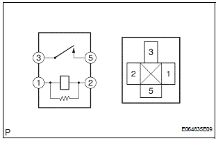
- Inspect IG1 relay continuity.
Resistance

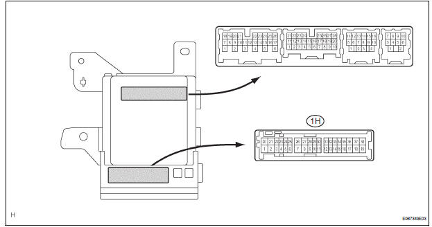
4 INSPECT INSTRUMENT PANEL JUNCTION BLOCK ASSEMBLY (ACC, IG)
- Measure the voltage between the terminals as shown in the chart below.
Voltage

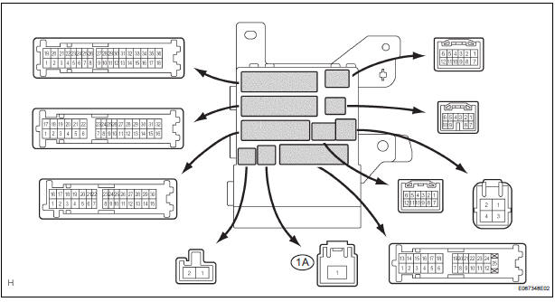
5 INSPECT INSTRUMENT PANEL JUNCTION BLOCK ASSEMBLY (+B)
- Measure voltage between the terminal 1A-1 of the instrument panel junction block assembly and body ground.
Voltage

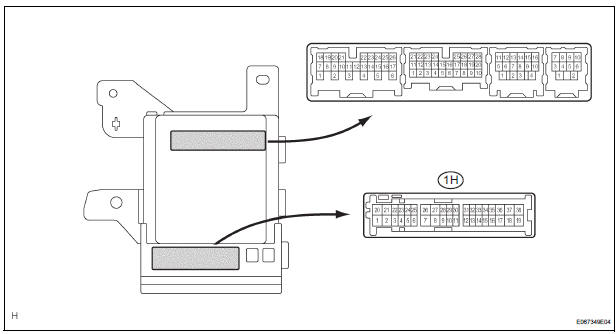
6 INSPECT INSTRUMENT PANEL JUNCTION BLOCK ASSEMBLY
- Measure voltage between the terminal 1H-10 of the instrument panel junction block assembly and body ground.
Voltage

REPAIR OR REPLACE HARNESS OR CONNECTOR
Test yourself
A quick Toyota Sienna quiz: every answer comes with an explanation and a link to the manual page.
Was this page helpful?