Lighting
Automatic Light Control Sensor Circuit
In this manual: Lighting
6steps
~36min
2/5difficulty
Done 0 of 6
DESCRIPTION
The Multiplex network body ECU receives the signal from the automatic light control sensor.
HINT: DTC code is output when malfunction of automatic light control sensor or open or short of automatic light control sensor circuit occurs.
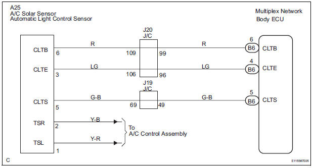
WIRING DIAGRAM
INSPECTION PROCEDURE
1 READ VALUE OF INTELLIGENT TESTER
- Connect the intelligent tester to DLC3.
- Turn the ignition switch ON and push the intelligent tester main switch ON.
- Select the items below in the DATA LIST, and read the displays on the intelligent tester
BODY NO.1:

2 CHECK HARNESS AND CONNECTOR (MULTIPLEX NETWORK BODY ECU - AUTOMATIC LIGHT CONTROL SENSOR)
- Check for open or short circuit in the harness and the connector between the terminal 6 of the automatic light control sensor and the terminal B6-6 of the multiplex network body ECU.
- Check for open or short circuit in the harness and the connector between the terminal 3 of the automatic light control sensor and the terminal B6-4 of the multiplex network body ECU.
- Check for open or short circuit in the harness and the connector between the terminal 5 of the automatic light control sensor and the terminal B6-5 of the multiplex network body ECU
3 INSPECT INSTRUMENT PANEL JUNCTION BLOCK ASSEMBLY
- Measure voltage between the terminal B6-4 and the terminal B6-6 of the multiplex network body ECU in the instrument panel junction block assembly.
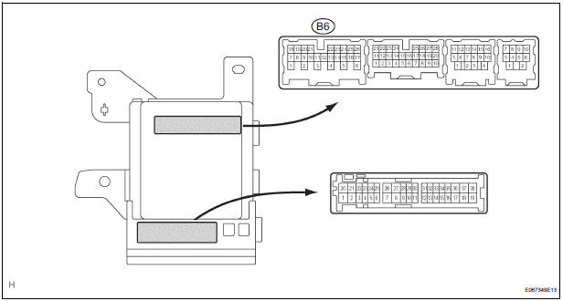
Voltage

PROCEED TO NEXT CIRCUIT INSPECTION SHOWN IN PROBLEM SYMPTOMS TABLE
Test yourself
A quick Toyota Sienna quiz: every answer comes with an explanation and a link to the manual page.
Was this page helpful?