TC and CG Terminal Circuit
DESCRIPTION
Connecting terminals TC and CG of the DLC3 causes the ECU to display the DTC by blinking the ABS warning light and/or VSC warning light.
WIRING DIAGRAM

INSPECTION PROCEDURE
NOTICE: When replacing the brake actuator assembly, perform zero point calibration (See page BC-70).
1 CHECK CAN COMMUNICATION SYSTEM
(a) Check if the CAN communication system DTC is output (See page BC-82).
Result


2 INSPECT DLC3
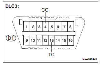
(a) Turn the ignition switch to the ON position.
(b) Measure the voltage according to the value(s) in the table below.
Standard voltage
Result 


3 CHECK HARNESS AND CONNECTOR (TC of DLC3 - ECM)
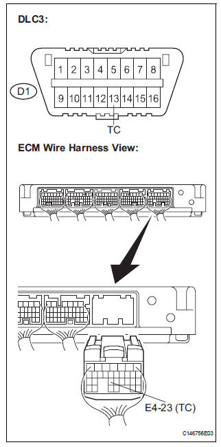
(a) Turn the ignition switch off.
(b) Disconnect the ECM connector.
(c) Measure the resistance according to the value(s) in the table below.
Standard resistance 


4 CHECK HARNESS AND CONNECTOR (CG of DLC3 - BODY GROUND)
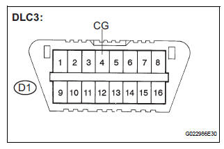
(a) Measure the resistance according to the value(s) in the table below.
Standard resistance


5 CHECK ECM (TC of DLC3 INPUT)
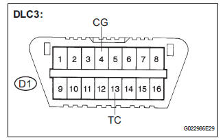
(a) Reconnect the ECM connector.
(b) Using SST, connect terminals TC and CG of the DLC3.
SST 09843-18040
(c) Turn the ignition switch to the ON position.
(d) Check that the check engine warning light is blinking.
Result 
HINT: If troubleshooting has been carried out according to the Problem Symptoms Table, refer back to the table and proceed to the next step before replacing the part (See page BC-79).


REPLACE BRAKE ACTUATOR ASSEMBLY
Test yourself
A quick Toyota Sienna quiz: every answer comes with an explanation and a link to the manual page.