Low Battery Positive Voltage
DTC C1241/41 Low Battery Positive Voltage
DESCRIPTION
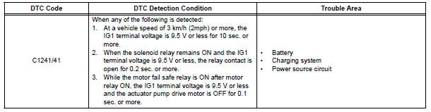
WIRING DIAGRAM
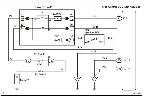
INSPECTION PROCEDURE
1 INSPECT ECU-IG FUSE
(a) Remove the ECU-IG fuse from the driver side J/B.
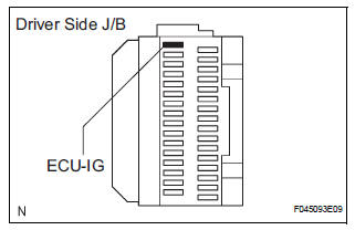
(b) Check continuity of the ECU-IG fuse.
Standard resistance


2 CHECK BATTERY
(a) Check the positive battery voltage.
Standard voltage: 11 to 14 V


3 INSPECT SKID CONTROL ECU (IG1 TERMINAL)
(a) WHEN USING INTELLIGENT TESTER: (1) Connect the intelligent tester to the DLC3.
(2) Start the engine.
(3) Select the DATA LIST mode on the intelligent tester.
ABS / VSC:
(4) Check that the voltage condition output from the ECU displayed on the intelligent tester.
OK: "Normal" is displayed.
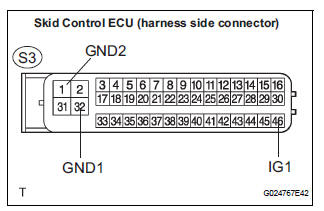
(b) WHEN NOT USING INTELLIGENT TESTER: (1) Disconnect the skid control ECU connector.
(2) Turn the ignition switch to the ON position.
(3) Measure the voltage according to the value(s) in the table below.
Standard voltage 
NOTICE: When replacing the brake actuator assembly, perform zero point calibration (See page BC-70).


REPLACE BRAKE ACTUATOR ASSEMBLY
4 INSPECT SKID CONTROL ECU (GND TERMINAL)
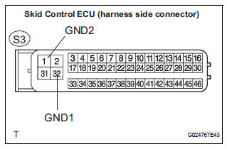
(a) Disconnect the skid control ECU connector.
(b) Measure the resistance according to the value(s) in the table below.
Standard resistance 


REPAIR OR REPLACE HARNESS OR CONNECTOR (IG1 CIRCUIT)
Test yourself
A quick Toyota Sienna quiz: every answer comes with an explanation and a link to the manual page.