Lighting (ext)
Headlight Dimmer Switch
Components COMPONENTS ILLUSTRATION 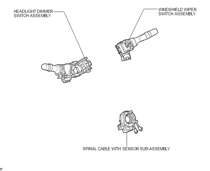 Removal REMOVAL PROCEDURE
1. REMOVE SPIRAL CABLE WITH SENSOR SUB-ASSEMBLY
(See page  )
2. REMOVE WINDSHIELD WIPER SWITCH ASSEMBLY
3. REMOVE HEADLIGHT DIMMER SWITCH ASSEMBLY
(a) Disconnect the connector. |
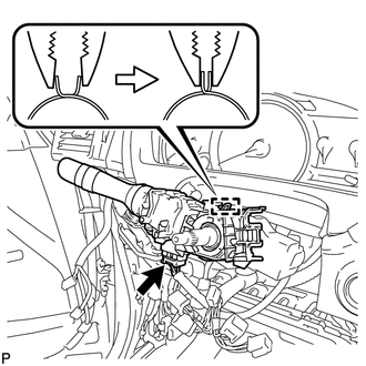 |
(b) Disengage the clamp as shown in the illustration.
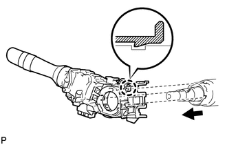
(c) Disengage the claw and remove the headlight dimmer switch assembly as shown in the illustration. |
 |
Inspection INSPECTION PROCEDURE
1. INSPECT HEADLIGHT DIMMER SWITCH ASSEMBLY
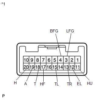
(a) Measure the resistance according to the value(s) in the table below.
Standard Resistance: Light Control Switch
Tester Connection | Switch Condition | Specified Condition |
12 (EL) - 18 (T) |
Light control switch off |
10 kΩ or higher |
18 (T) - 19 (A) |
Light control switch off |
10 kΩ or higher |
19 (A) - 20 (H) |
Light control switch off |
10 kΩ or higher |
12 (EL) - 18 (T) |
Light control switch in tail position |
Below 1 Ω |
12 (EL) - 18 (T) |
Light control switch in head position |
Below 1 Ω |
18 (T) - 20 (H) |
Light control switch in head position |
Below 1 Ω |
12 (EL) - 19 (A) |
Light control switch in auto position |
Below 1 Ω |
Dimmer Switch
Tester Connection | Switch Condition | Specified Condition |
11 (HU) - 12 (EL) |
Dimmer switch in high position |
Below 1 Ω |
12 (EL) - 11 (HU) |
Dimmer switch in high flasher position |
Below 1 Ω |
12 (EL) - 17 (HF) |
Below 1 Ω |
Turn Signal Switch
Tester Connection | Switch Condition | Specified Condition |
12 (EL) - 13 (TR) |
Right turn |
Below 1 Ω |
12 (EL) - 13 (TR) |
Neutral |
10 kΩ or higher |
12 (EL) - 15 (TL) |
Neutral |
10 kΩ or higher |
12 (EL) - 15 (TL) |
Left turn |
Below 1 Ω |
Fog Light Switch
Tester Connection | Switch Condition | Specified Condition |
3 (LFG) - 4 (BFG) |
Fog light switch off |
10 kΩ or higher |
3 (LFG) - 4 (BFG) |
Fog light switch on |
Below 1 Ω |
Text in Illustration
*1 |
Component without harness connected
(Headlight Dimmer Switch Assembly) |
If the result is not as specified, replace the headlight dimmer switch assembly. |
 |
Installation INSTALLATION PROCEDURE
1. INSTALL HEADLIGHT DIMMER SWITCH ASSEMBLY
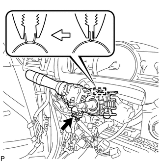
(a) Install the headlight dimmer switch assembly as shown in the illustration. |
 |
(b) Engage the claw.
(c) Install the headlight dimmer switch assembly with the clamp. |
 |
(d) Connect the connector.
2. INSTALL WINDSHIELD WIPER SWITCH ASSEMBLY

3. INSTALL SPIRAL CABLE WITH SENSOR SUB-ASSEMBLY
(See page )
?
Test yourself
A quick Toyota Venza quiz: every answer comes with an explanation and a link to the manual page.
Was this page helpful?