Stop Light Switch
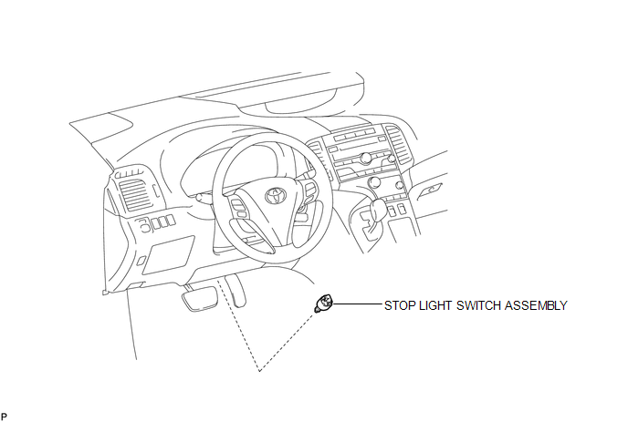
Removal REMOVAL PROCEDURE
1. REMOVE STOP LIGHT SWITCH ASSEMBLY
(a) Disconnect the connector. |
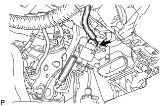 |
(b) Turn the stop light switch assembly counterclockwise and remove the stop light switch assembly. |
 |
1. INSPECT STOP LIGHT SWITCH ASSEMBLY
(a) Measure the resistance according to the value(s) in the table below.

Standard Resistance:
Tester Connection | Switch Condition | Specified Condition |
|---|---|---|
1 - 2 |
Pushed |
10 kΩ or higher |
Not pushed |
Below 1 Ω |
|
3 - 4 |
Pushed |
Below 1 Ω |
Not pushed |
10 kΩ or higher |
*1 |
Component without harness connected (Stop Light Switch Assembly) |
If the result is not as specified, replace the stop light switch assembly.
Installation INSTALLATION PROCEDURE1. INSTALL STOP LIGHT SWITCH ASSEMBLY
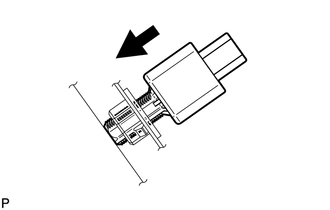
(a) Insert the stop light switch assembly until the rod hits the pedal. NOTICE: When inserting the stop light switch assembly, support the pedal from behind so that the pedal is not depressed. |
 |
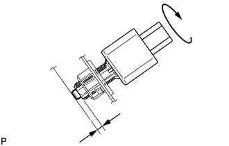
(b) Make a quarter turn clockwise to install the stop light switch assembly. Torque: 1,5 N·m {15 kgf·cm, 13 in·lbf} or less NOTICE: When inserting the stop light switch assembly, support the pedal from behind so that the pedal is not depressed. |
 |
(c) Connect the connector.
(d) Check the protrusion of the rod.
Protrusion of the rod:
1.5 to 2.5 mm (0.0591 to 0.0984 in.)
If the protrusion is not as specified, adjust it.
NOTICE:
Do not depress the brake pedal.
Test yourself
A quick Toyota Venza quiz: every answer comes with an explanation and a link to the manual page.