Height Control Sensor
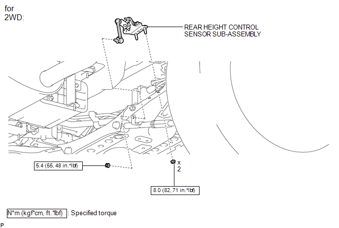
ILLUSTRATION
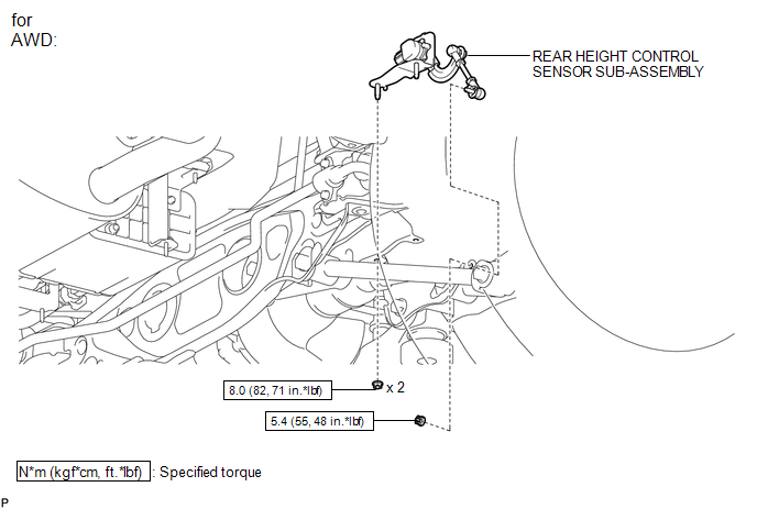
Removal REMOVAL PROCEDURE
1. REMOVE REAR HEIGHT CONTROL SENSOR SUB-ASSEMBLY (for 2WD)
(a) Disconnect the connector. |
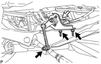 |
(b) Remove the 3 nuts and rear height control sensor sub-assembly.
2. REMOVE REAR HEIGHT CONTROL SENSOR SUB-ASSEMBLY (for AWD)
(a) Disconnect the connector. |
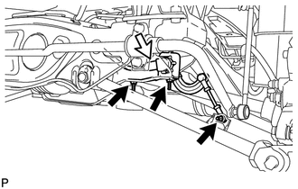 |
(b) Remove the 3 nuts and rear height control sensor sub-assembly.
Inspection INSPECTION PROCEDURE1. INSPECT REAR HEIGHT CONTROL SENSOR SUB-ASSEMBLY RH (for 2WD)
(a) Connect 3 dry cell batteries (1.5 V) in series. |
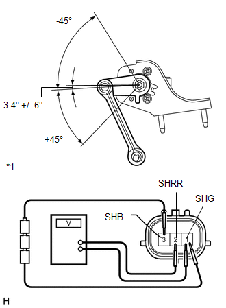 |
(b) Connect a positive (+) lead from the batteries to terminal 3 (SHB) and a negative (-) lead from the batteries to terminal 1 (SHG).
(c) Measure the voltage between terminals 2 (SHRR) and 1 (SHG) while slowly moving the link up and down.
Standard Voltage:
Tester Connection | Condition | Specified Condition |
|---|---|---|
2 (SHRR) - 1 (SHG) |
+45° (High) |
4.05 V |
2 (SHRR) - 1 (SHG) |
0° (normal) |
2.25 V |
2 (SHRR) - 1 (SHG) |
-45° (Low) |
0.45 V |
*1 |
Component without harness connected (Rear Height Control Sensor Sub-assembly RH) |
If the result is not as specified, replace the rear height control sensor sub-assembly RH.
2. INSPECT REAR HEIGHT CONTROL SENSOR SUB-ASSEMBLY RH (for AWD)
(a) Connect 3 dry cell batteries (1.5 V) in series. |
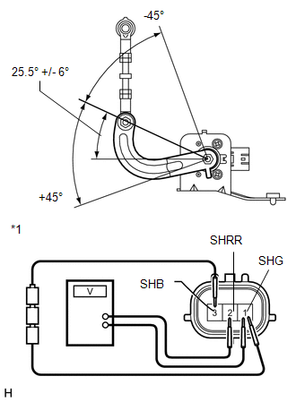 |
(b) Connect a positive (+) lead from the batteries to terminal 3 (SHB) and a negative (-) lead from the batteries to terminal 1 (SHG).
(c) Measure the voltage between terminals 2 (SHRR) and 1 (SHG) while slowly moving the link up and down.
Standard Voltage:
Tester Connection | Condition | Specified Condition |
|---|---|---|
2 (SHRR) - 1 (SHG) |
+45° (High) |
4.05 V |
2 (SHRR) - 1 (SHG) |
0° (normal) |
2.25 V |
2 (SHRR) - 1 (SHG) |
-45° (Low) |
0.45 V |
*1 |
Component without harness connected (Rear Height Control Sensor Sub-assembly RH) |
If the result is not as specified, replace the rear height control sensor sub-assembly RH.
Installation INSTALLATION PROCEDURE1. INSTALL REAR HEIGHT CONTROL SENSOR SUB-ASSEMBLY (for 2WD)
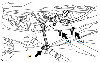
(a) Install the rear height control sensor sub-assembly with the 3 nuts. Torque: Nut (A) : 8 N·m {82 kgf·cm, 71 in·lbf} Nut (B) : 5,4 N·m {55 kgf·cm, 48 in·lbf} |
 |
(b) Connect the connector.
2. INSTALL REAR HEIGHT CONTROL SENSOR SUB-ASSEMBLY (for AWD)
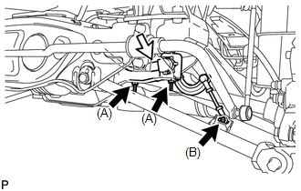
(a) Install the rear height control sensor sub-assembly with the 3 nuts. Torque: Nut (A) : 8 N·m {82 kgf·cm, 71 in·lbf} Nut (B) : 5,4 N·m {55 kgf·cm, 48 in·lbf} |
 |
(b) Connect the connector.
3. HEIGHT CONTROL SENSOR SIGNAL INITIALIZATION
(See page  )
4. PREPARE VEHICLE FOR HEADLIGHT AIM ADJUSTMENT
5. PREPARE FOR HEADLIGHT AIMING
6. INSPECT HEADLIGHT AIMING
7. ADJUST HEADLIGHT AIMING
Test yourself
A quick Toyota Venza quiz: every answer comes with an explanation and a link to the manual page.