Automatic Light Control Sensor

Removal REMOVAL PROCEDURE
1. REMOVE DEFROSTER NOZZLE GARNISH

2. REMOVE AUTOMATIC LIGHT CONTROL SENSOR
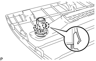
(a) Disengage the 2 claws and remove the automatic light control sensor. |
 |
1. INSPECT AUTOMATIC LIGHT CONTROL SENSOR
(a) Disconnect the F4 automatic light control sensor connector. |
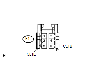 |
(b) Measure the voltage and resistance according to the value(s) in the table below.
Standard Voltage:
Tester Connection | Condition | Specified Condition |
|---|---|---|
F4-6 (CLTB) - F4-3 (CLTE) |
Ignition switch off |
Below 1 V |
Ignition switch ON |
10 to 14 V |
Standard Resistance:
Tester Connection | Condition | Specified Condition |
|---|---|---|
F4-3 (CLTE) - Body ground |
Always |
Below 1 Ω |
*1 |
Front view of wire harness connector (to Automatic Light Control Sensor) |
If the result is not as specified, there may be a malfunction on the wire harness side.
(c) Reconnect the F4 automatic light control sensor connector. |
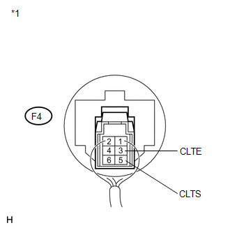 |
(d) Connect an oscilloscope to the automatic light control sensor connector.
Text in Illustration*1 |
Component with harness connected (Automatic Light Control Sensor) |
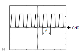
(e) Check the waveform. OK:
HINT: If the ambient light becomes brighter, width A becomes narrower. If the result is not as specified, replace the automatic light control sensor. |
 |
1. INSTALL AUTOMATIC LIGHT CONTROL SENSOR
(a) Engage the 2 claws to install the automatic light control sensor. |
 |
2. INSTALL DEFROSTER NOZZLE GARNISH

Test yourself
A quick Toyota Venza quiz: every answer comes with an explanation and a link to the manual page.