Turn Signal Flasher Assembly
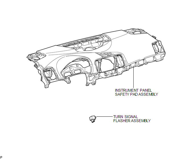
Inspection INSPECTION PROCEDURE
1. INSPECT TURN SIGNAL FLASHER ASSEMBLY
(a) Disconnect the D34 turn signal flasher assembly connector. |
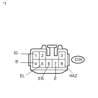 |
(b) Measure the voltage according to the value(s) in the table below.
Standard Voltage:
Tester Connection | Condition | Specified Condition |
|---|---|---|
D34-1 (IG) - Body ground |
Ignition switch off |
Below 1 V |
Ignition switch ON |
11 to 14 V |
|
D34-4 (B) - Body ground |
Always |
11 to 14 V |
*1 |
Front view of wire harness connector (to Turn Signal Flasher Assembly) |
If the result is not as specified, repair or replace the wire harness or connector.
(c) Measure the resistance according to the value(s) in the table below.
Standard Resistance:
Tester Connection | Condition | Specified Condition |
|---|---|---|
D34-5 (EL) - Body ground |
Turn signal switch off |
10 kΩ or higher |
Turn signal switch in left turn position |
Below 1 Ω |
|
D34-6 (ER) - Body ground |
Turn signal switch in neutral position |
10 kΩ or higher |
Turn signal switch in right turn position |
Below 1 Ω |
|
D34-7 (E) - Body ground |
Always |
Below 1 Ω |
D34-8 (HAZ) - Body ground |
Hazard warning switch off |
10 kΩ or higher |
Hazard warning switch on |
Below 1 Ω |
If the result is not as specified, repair or replace the wire harness or connector.
(d) Reconnect the D34 turn signal flasher assembly connector. |
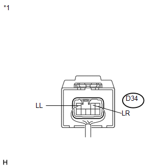 |
(e) Measure the voltage according to the valve(s) in the table below.
Standard Voltage:
Tester Connection | Condition | Specified Condition |
|---|---|---|
D34-2 (LR) - Body ground |
Hazard warning switch off |
Below 1 V |
Hazard warning switch on |
11 to 14 V (60 to 120 times per minute) |
|
Turn signal switch off |
Below 1 V |
|
Ignition switch ON and turn signal switch in RH position |
11 to 14 V (60 to 120 times per minute) |
|
D34-3 (LL) - Body ground |
Hazard warning switch off |
Below 1 V |
Hazard warning switch on |
11 to 14 V (60 to 120 times per minute) |
|
Turn signal switch off |
Below 1 V |
|
Ignition switch ON and turn signal switch in LH position |
11 to 14 V (60 to 120 times per minute) |
*1 |
Component with harness connected (Turn Signal Flasher Assembly) |
If the result is not as specified, replace the turn signal flasher assembly.
Removal REMOVAL PROCEDURE1. REMOVE INSTRUMENT PANEL SAFETY PAD ASSEMBLY
HINT:
Refer to the procedure up to Remove Instrument Panel Safety Pad Assembly (See page  ).
2. REMOVE TURN SIGNAL FLASHER ASSEMBLY
(a) Disconnect the connector. |
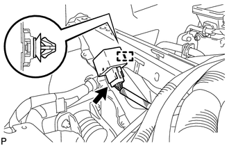 |
(b) Disengage the clamp and remove the turn signal flasher assembly.
Installation INSTALLATION PROCEDURE1. INSTALL TURN SIGNAL FLASHER ASSEMBLY
(a) Engage the clamp to install the turn signal flasher assembly. |
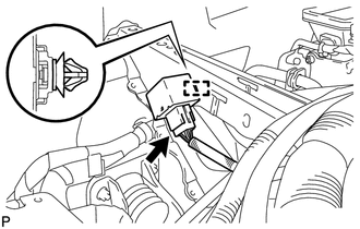 |
(b) Connect the connector.
2. INSTALL INSTRUMENT PANEL SAFETY PAD ASSEMBLY
HINT:
Refer to the procedure from Install Instrument Panel Safety Pad Assembly (See page  ).
Test yourself
A quick Toyota Venza quiz: every answer comes with an explanation and a link to the manual page.