4- cylinder injection engine(1.4 1 direct inction. turbocharger)
Removing and installing sealing flange on gearbox side
In this manual: 4- cylinder injection engine(1.4 1 direct inction. turbocharger)
~8min read
Special tools and workshop equipment required |
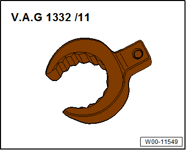
Flared ring spanner tool insert AF 24 -V.A.G 1332/11- |
 |
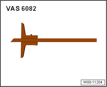
Depth gauge -VAS 6082- |
 |
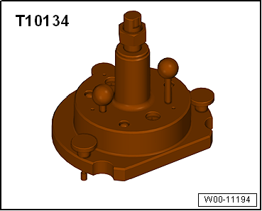
Assembly tool -T10134- |
 |
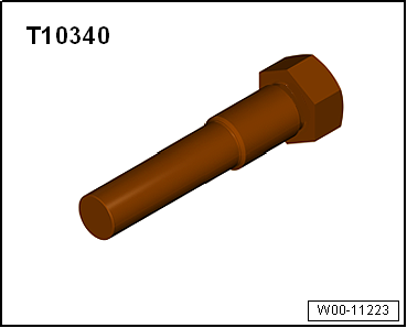
Locking pin -T10340-Bolt M6x35 (3x)ProcedureGearbox removed.
|
 |
Setting crankshaft to “TDC” position:
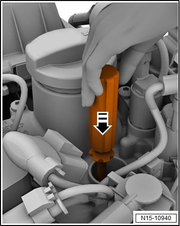
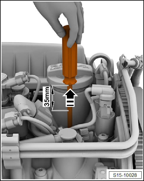
Setting correct position of crankshaft for screwing in locking pin: |
 |
|
 |
|
 |
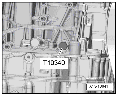
Risk of damage to engineIf locking pin -T10340- cannot be screwed in as far as stop, this indicates that crankshaft is not in the correct position!In this case, proceed as follows:Unscrew locking pin.Turn crankshaft 90° in direction of engine rotation.Screw locking pin -T10340- into cylinder block as far as stop and tighten to 30 N·m.Turn crankshaft in direction of engine rotation as far as stop.
The locking pin now rests against the crank web. Note Locking pin -T10340- locks crankshaft in direction of engine rotation only.
|
 |
|
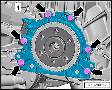 |
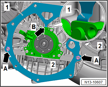
Note The sealing flange -1- is pressed off crankshaft -3- together with the sender wheel -2-.
Pressing in sealing flange with sender wheel Note |
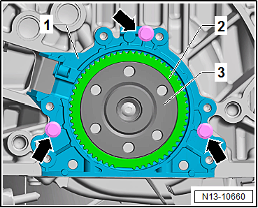 |
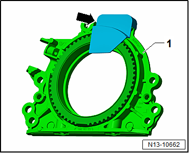
| The sealing flange with a PTFE seal is equipped with a sealing lip support ring -2-. This support ring serves as a fitting sleeve and must not be removed prior to installation. Sealing flange and sender wheel -1- must not be separated or turned after removal from packaging. The sender wheel -1- is held in its installation position on the locating pin of the assembly tool -T10134- → Anchor. Sealing flange and oil seal form one unit and must only be renewed together with the sender wheel. The assembly tool -T10134- is held in its position relative to the crankshaft by a guide pin inserted into a hole in the crankshaft → Anchor. | 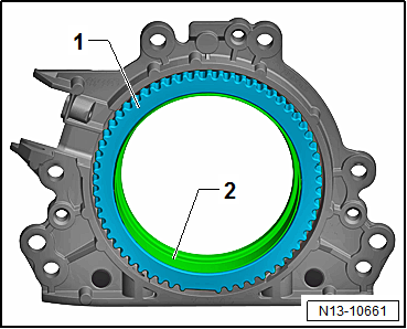 |
Components of assembly tool -T10134-:
|
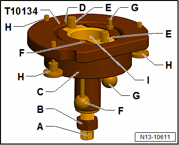 |
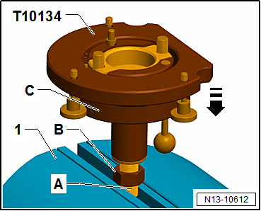
Fitting sealing flange with sender wheel on assembly tool -T10134-:
|
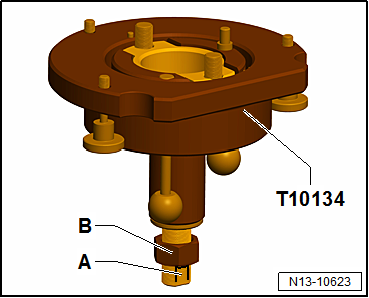 |
Inner part of assembly tool and assembly housing must be at same height. |
 |
Note Do not take the sender wheel out of the sealing flange or rotate it out of position. |
 |
|
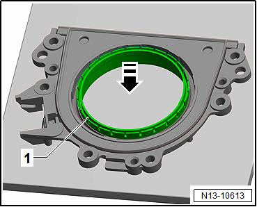 |
| Upper edge of sealing lip support ring -1- and front edge of sealing flange -2- must align -arrows-. | 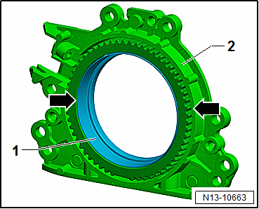 |
The sealing flange must rest flat against the assembly tool. |
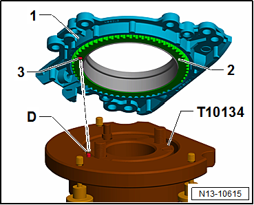 |
|
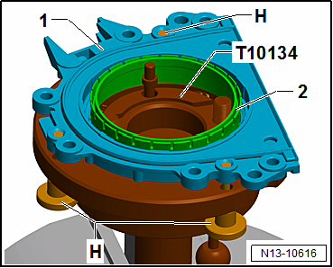 |
Mounting assembly tool -T10134- with sealing flange -1- on crankshaft flange:The crankshaft flange must be free of grease and oil.Engine is at “TDC” position → Anchor.
|
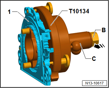 |
|
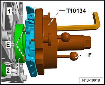 |
|
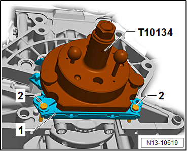 |
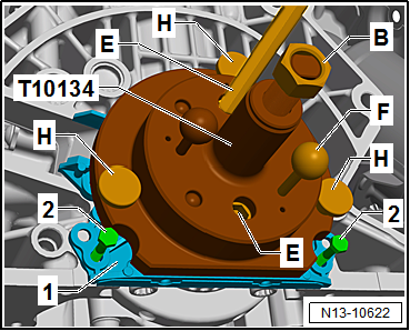
Bolting assembly tool -T10134- onto crankshaft flange:
Note The guide pin for diesel engines (black knob) must not be inserted in threaded hole of crankshaft.
|
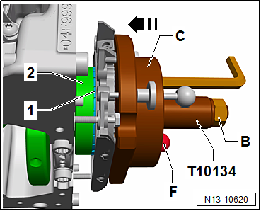 |
Pressing sender wheel onto crankshaft flange using assembly tool -T10134-:
|
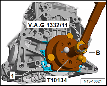 |
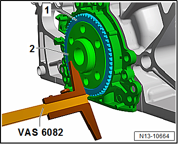
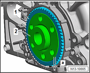
Checking sender wheel installation position on crankshaft:
|
 |
|
 |
Specification: dimension -a- = 0.5 mm
|
 |
Re-pressing sender wheel:
|
|
Reassembly
Specified torques→ Fig. „“Sealing flange on gearbox side - specified torque and tightening sequence”“→ Fig. „“Plug for TDC drilling in cylinder block at rear – specified torque”“→ Chapter „Assembly overview - cylinder block, gearbox end“Engine speed sender -G28- → Chapter „Assembly overview - ignition system“ |
|
Test yourself
A quick Volkswagen Golf quiz: every answer comes with an explanation and a link to the manual page.
Was this page helpful?