Transmission, Disassembling and Assembling
Schematic Overview - Transmission
Schematic Overview - Transmission, FWD
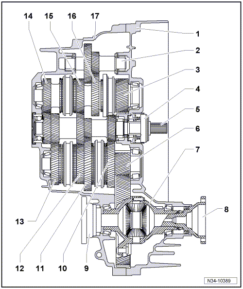
- Clutch Housing
- Reverse Shaft
- 5th, 6th and Reverse Gear Output Shaft
- Clutch Slave Cylinder with Release Bearing
- Input Shaft
- 1st through 4th Gear Output Shaft
- Differential
- Right Flange Shaft
- Left Flange Shaft
- 2nd Gear Wheel
- 1st Gear Wheel
- 4th Gear Wheel
- 3rd Gear Wheel
- 5th Gear Wheel
- 6th Gear Wheel
- Reverse Gear Wheel
- Transmission Housing
Overview - Transmission
Overview - Transmission, FWD

I. Chapter "Overview - Transmission Housing and Selector Mechanism"
I. Chapter "Overview - Shift Unit"
II. Chapter "Overview - Shafts, Differential, Gear Shift, FWD Vehicles"
II. Chapter "Overview - Shift Forks"
Overview - Transmission Housing and Selector Mechanism
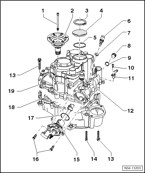
- Bolt
- Removing and installing.
- Left Flange Shaft
- With pressure spring and tapered ring
- Removing and installing.
- FWD, Assembling.
- AWD, Assembling.
- Circlip
- For the metal cover
- Not used in plastic covers
- Cap
- Replace after removing
- Made of metal or plastic.
- Secured with metal locking ring
- Without plastic locking ring
- Allocate the components using the Parts Catalog.
- Circlip
- For the grooved ball bearing/input shaft.
- The thickness must be determined again.
- Back-Up Lamp Switch -F4-
- 20 N·m
- Replace after removing
- With permanent seal
- Seal
- Replace after removing
- Not installed on all transmissions
- If present, replace after removing
- Oil Drain Plug
- Tightening Specification.
- Seal
- Replace after removing
- Bolt
- 6 N·m
- Transmission Neutral Position Sensor -G701-
- For vehicles with the Start/Stop System
- Locking Bolt
- Metal locking screw 45 N·m
- Plastic locking screw 30 N·m
- Replace locking screw after removing
- For the selector shaft
- Metal or plastic locking screw
- Bolt
- 15 N·m and turn an additional 180º
- Replace after removing
- M9 aluminum bolt
- Bolt
- 15 N·m and turn an additional 180º
- Replace after removing
- M9 aluminum bolt
- Gearshift Unit
- (Gearshift shaft with gearshift cover).
- Removing and installing with the transmission installed:
- Vehicles with a turbo diesel engine, remove the entire air filter housing.
- If the vehicle has a gasoline engine, remove the entire air filter housing.
- Remove the battery and the battery tray if necessary.
- The locking elbow -item 6- for adjusting the shift mechanism must not be engaged
- Remove the cables and gearshift lever.
- Remove the locking screw.
- If equipped, remove the Transmission Neutral Position Sensor -G701-.
- Remove bolts and shift unit
- Install in reverse order of removal. Replace the O-ring and bolts.
- Bolt
- 20 N·m
- Replace after removing
- O-Ring
- Replace after removing
- Clutch Housing
- Servicing.
- Transmission Housing
- Servicing.
Overview - Shift Unit
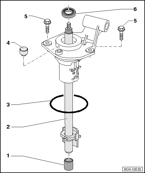
- Bearing Bushing
- For the selector shaft
- Removing and installing.
- Gearshift Unit
- Consisting of the gearshift shaft and the gearshift cover
- The components cannot be separated from each other
- Can be removed and installed with the transmission installed.
- O-Ring
- Insert in the groove in the shift cover
- Install with transmission fluid
- Replace after removing
- Cap
- For the transmission ventilation
- Bolt
- For the shift unit to the transmission housing
- Tightening Specification.
- Replace after removing
- Gearshift Shaft Seal
- Replace after removing.
Overview - Shafts, Differential, Gear Shift
Overview - Shafts, Differential, Gear Shift, FWD Vehicles

- 1st through 4th Gear Output Shaft
- Disassembling and Assembling.
- Installation position.
- Gearshift Rod with 1st Gear and 2nd Gear Shift Fork
- Installation position.
- Gearshift Rod with 3rd Gear and 4th Gear Shift Fork
- Installation position.
- 5th, 6th and Reverse Gear Output Shaft
- Disassembling and Assembling.
- Installation position.
- Gearshift Rod with 5th Gear and 6th Gear Shift Fork
- Installation position.
- Reverse Gear Shift Fork
- Installation position.
- Input Shaft
- Installation position.
- Disassembling and Assembling.
- Replace grooved ball bearing on drive axle after removing.
- Thrust Washer
- Place on the reverse shaft
- Reverse Shaft
- Thrust Washer
- Bleeder
- Connect with clutch slave cylinder
- Clutch Housing
- Servicing.
- Input Shaft Seal
- Replace after removing.
- O-Ring
- Install on the line connection
- Coat with brake fluid before installing
- Clutch Slave Cylinder with Release Bearing
- Bolt
- Quantity: 3
- Replace after removing
- Removing and installing.
- Bolt
- Tightening Specification.
- Right Flange Shaft
- With pressure spring and tapered ring
- Removing and installing.
- Assembling.
- Differential
- Disassembling and Assembling.
Shafts and Gearshift Rods in Transmission Installation location
- Input Shaft
- 1st through 4th Gear Output Shaft
- 5th, 6th and Reverse Gear Output Shaft
- Reverse Shaft
- 3rd and 4th Gear Gearshift Rod
- 1st and 2nd Gear Gearshift Rod
- 5th and 6th Gear Gearshift Rod
- Reverse Gear Shift Fork

The Reverse Gear Shift Fork -D- is Mounted on the 5th and 6th Gear Gearshift Rod -C-.
Overview - Shift Forks

- Rubber Damper
- Remove from the gearshift rod by hand and install.
- Gearshift Rod with 1st Gear and 2nd Gear Shift Fork
- Gearshift Rod with 3rd Gear and 4th Gear Shift Fork
- Gearshift Rod with 5th Gear and 6th Gear Shift Fork
- Reverse Gear Shift Fork
- Is mounted on the gearshift rod with the 5th and 6th gear shift fork.
Selector Shaft Seal, Replacing
Special tools and workshop equipment required
- Press Piece - Shift Rod/Alternator -VW423-
- Puller - Crankshaft/Power Steering Seal -T20143/1-
- Sealing Grease
- Grease allocation. Refer to the Parts Catalog.
- Remove gearshift lever and selector relay lever.
Note
If it is not possible to remove the selector relay lever through the transmission bracket, then remove the sliding shoe from the gearshift lever.
- Remove the gearshift lever from the gearshift shaft.
- Remove the seal using the Puller - Crankshaft/Power Steering Seal -T20143/1-
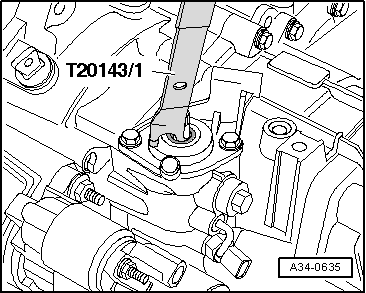
- Lightly oil the new gasket on the outer circumference.
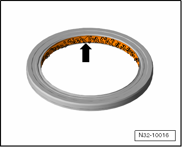
- Fill the area between the sealing lip and dust lip -arrow- halfway with Sealing Grease.
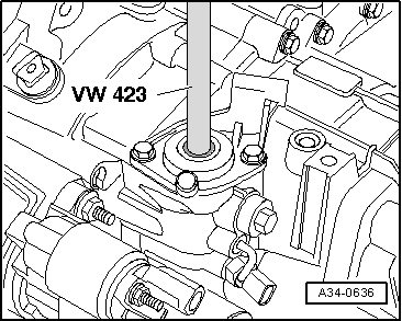
- Drive in the seal using the Press Piece - Shift Rod/Alternator -VW423-.
- Install gearshift lever and selector relay lever.
Transmission, Disassembling and Assembling
Remove and Install Transmission Housing, Gearshift Mechanism, Input Shaft, Output Shafts, Differential, Selector Rods and Bevel Box, If Necessary.
Remove and Install Transmission Housing, Gearshift Mechanism, Input Shaft, Output Shafts, Differential, Selector Rods and Bevel Box, If Necessary.
Special tools and workshop equipment required
- Holding Plate -VW309A-
- or Holding Plate -VW309A-
- Holding Fixture -VW313-
- Transmission Support -VW353-
- Press Piece - Multiple Use -VW455- or Press Piece - Front Wishbone -3160-
- Slide Hammer Set -VW771-
- -1-Puller - Kukko Internal - 12-16mm -21/01-
- -3-Puller - Kukko Quick Action Separating Tool - 5-60mm -17/0-
- -4-Puller - Kukko Counterstay -22/1-
- Bracket - Multiple Use -30-211A-
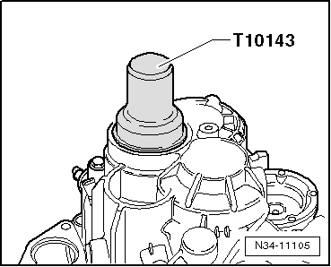
- Seal Installer - Drive Flange -T10143- or Seal Installer - Output Shaft Oil Seal -T10180-
- Locking Sleeve Drift -T10169-
- or Locking Sleeve Drift - T10362-.
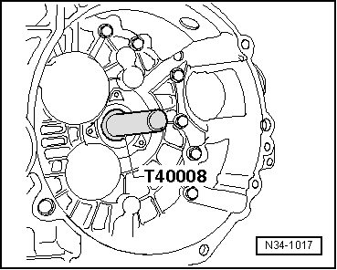
- Seal Installer - Drive Axle -T40008-
- Torque Wrench 1331 5-50Nm -VAG1331-
- Hot Air Blower -VAG1416-
- Pry Lever -80-200-
- Drip Tray -VAG1306-
- or Shop Crane - Drip Tray -VAS6208-
- Sealant
- Allocation. Refer to the Parts Catalog.
Transmission, Disassembling
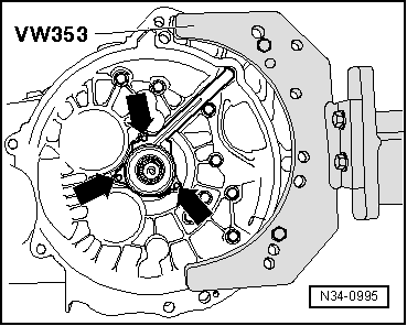
- Secure the transmission on the Transmission Support -VW353--arrows-.

Note
If one of the fastening holes does not touch the Transmission Support, place washers between the fastening hole and the Transmission Support.
- Turn the transmission the assembly stand with the oil drain plug facing down.
- Place the Drip Tray underneath.
- Drain gear oil from manual transmission.
AWD Transmission and FWD Transmission with Front Axle Differential Lock
- Remove right flange shaft countersunk screw with Socket and Key.
- Remove the four bolts -arrows- attaching the bevel box or the front axle differential lock to the manual transmission (only three bolts are shown in the illustration).
- Carefully press bevel box or front axle differential lock off manual transmission while protecting it against falling through.
- Note the transportation of the front axle differential lock.

FWD Transmission without Front Axle Differential Lock
- Remove the right flange shaft (the illustration shows the left flange shaft).
- Remove the flange shaft with the pressure spring.
Continuation for All
- Remove the clutch slave cylinder with the release bearing -arrows-.
- Transmission on vehicles with Stop/Start system: remove the Transmission Neutral Position Sensor -G701--arrow-.
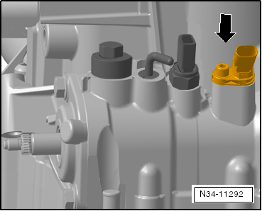
Make Sure during the following Step That the Gearshift Shaft Is Not Blocked by the Locking Elbow -arrow-.
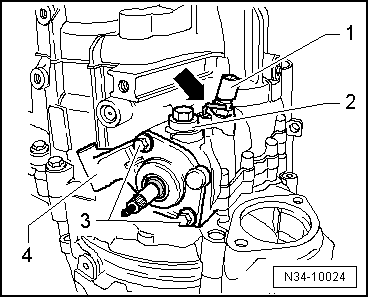
- Move the gearshift shaft into neutral.
- Remove the Back-Up Lamp Switch -F4--1-.
- Remove the locking bolt -2-.
- Then remove the bolts -3-.
- Remove selector shaft with shift cover -4- from transmission housing.
Note
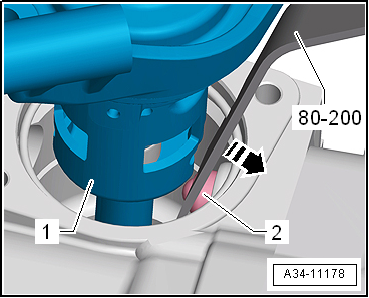
Use the Pry Lever -80-200- to press against the spring force of the securing bushing direction of -arrow- so that the gearshift shaft -1- does not touch the securing bushing -2- when removing.

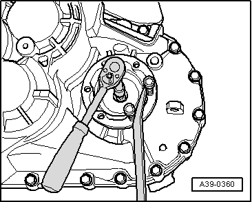
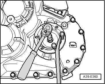
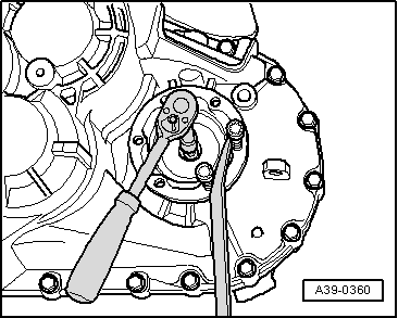
- Remove the left flange shaft bolt. To do this, install two bolts in the flange and counterhold it using a tire iron.
- Remove the flange shaft with the pressure spring.
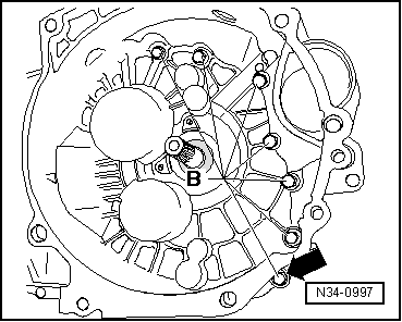
- Remove the bolts -B- that connect the clutch housing to the transmission housing.
Note
One bolt -arrow- is located outside of the bolting flange.
- Lock the input shaft as follows:
The Stub Shaft Splines on the Input Shaft Have Different Lengths on the Transmission.
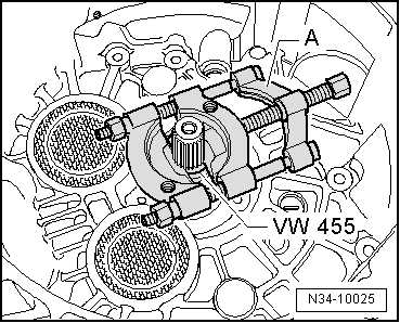
- Either place the Press Piece - Multiple Use -VW455- over the input shaft on the clutch housing.

- Or place the Press Piece - Front Wishbone -3160- over the input shaft on the clutch housing.
- Tension the Separating Tool - 5-60mm-A-, for example Puller - Kukko Quick Action Separating Tool - 5-60mm -17/0-, tightly behind the splines on the input shaft.
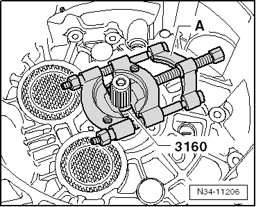
The back of the Separating Tool - 5-60mm must touch the Press Piece - Multiple Use -VW455- or the Press Piece - Front Wishbone -3160- free-of-play.
Note
Metal and plastic covers are installed for the input shaft.
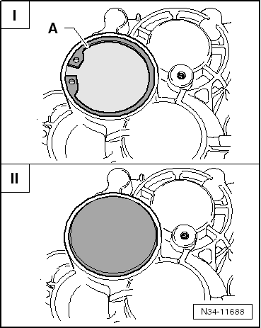
The locking ring -A- has been discontinued together with the plastic cover for the input shaft.
- -I- = Steel cover for the input shaft with locking ring -A-
- -II- = Plastic cover for the input shaft without locking ring
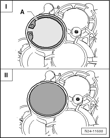
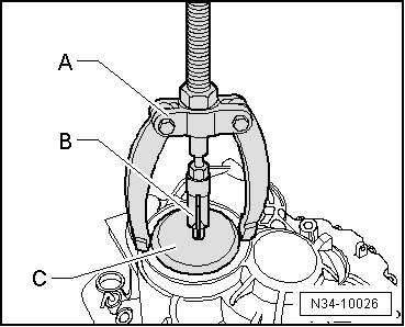
Metal Cover
- Remove the cap/input shaft circlip -A-.

- Pierce the rubber piece in the center of the cover -C- using a Screwdriver.
Caution
There is a risk of damaging the components underneath the cover.
- Remove the cover from the transmission housing.
- Counter Support, for example Puller - Kukko Counterstay -22/1-
- Internal Puller 8 to 12 mm -21/01-, for example.
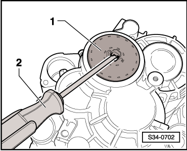
Note
Pry the cap -1- off with a screwdriver -2-.
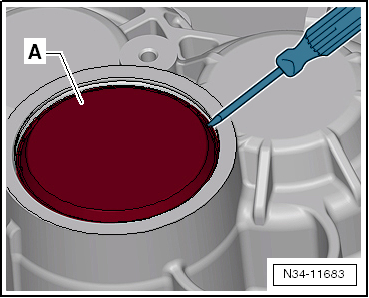
Plastic Cover
Carefully remove all tabs -A-. Do not damage the transmission housing when doing so.
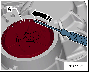
- Remove the cap -A-.
Make sure the individual parts of the cover are removed, if necessary.
Continuation for All
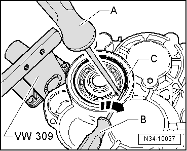
Remove the locking ring -C- from the grooved ball bearing on the input shaft/transmission housing as follows:
- Hold one end of the locking ring secure with the Screwdriver-A-.
- Pry the other end out of the groove in the grooved ball bearing in direction of -arrow- using the Screwdriver-B-.
- Pry out the rest of the locking ring using the Screwdriver-B-.
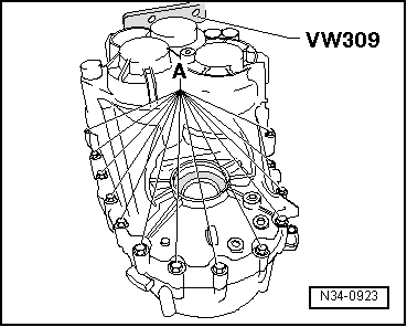
- Remove the bolts -A- that attach the transmission housing to the clutch housing.
- Install Adapter VW771/40 into the threaded hole in the transmission housing.
- Heat the transmission housing in the area near the bearing seat for the grooved ball bearing/input shaft to approximately 100 ºC (212 ºF) for approximately 10 minutes using a Hot Air Blower -VAG1416-, for example.
- Remove the transmission housing from the clutch housing in direction of -arrow- using Slide Hammer -VW771/1-.

Note
Pry off the transmission housing carefully at the protruding braces using a pry lever and alternating from side to side. Do not damage sealing surface.
- Remove the Separating Tool-A- and the Press Piece - Multiple Use - VW455- or the Press Piece - Front Wishbone -3160- from the input shaft.
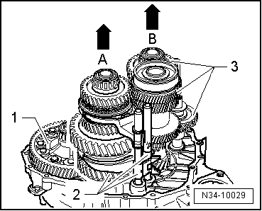
A second technician is needed to help remove the shafts from the clutch housing.
- Lift the differential -1- with the left hand. With the right hand, lift the output shaft for 1st to 4th gear together with the gearshift rods -2--arrow A-.
- At the same time, the second technician lifts the input, reverse, and output shafts for 5th/6th gear and reverse gear -3- together with the gearshift rod out of the clutch housing -arrow B-.
Note
If necessary, differential can be shifted again in clutch housing after lifting shafts.
- Remove the input shaft seal.
Note
Replace grooved ball bearing on drive axle after removing.
Assembling the Transmission
- A new grooved ball bearing is pressed onto the input shaft.
- The reverse gear shift fork -1- is placed on the 5th and 6th gear gearshift rod -2-.
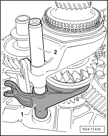
- Install the input shaft -1-, the 5th/6th gear output shaft -2- together with the 5th/6th gear gearshift rod -3-, the reverse gear shift fork -4- and reverse shaft -5-.
The shift jaw -arrow A- on the reverse gear shift fork faces the outside of the transmission. The shift jaw -arrow B- on the 5th/6th gear gearshift rod must face toward the inside of the transmission.
- Then install the differential -1-.
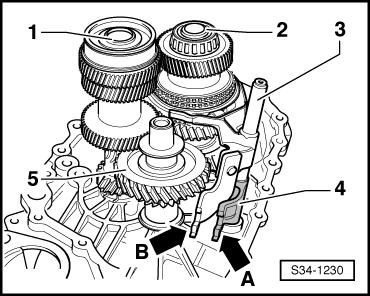
Note
A second technician is needed to help install the shafts into the clutch housing.
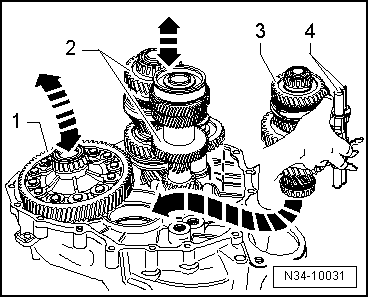
- Hold the 1st through 4th gear output shaft -3- with the gearshift rods -4- in the right hand as illustrated.
- Lift the differential slightly with your left hand.
- Have the second technician slightly lift the input shaft and the 5th/6th gear output shaft -2- together with the reverse shaft at the same time.
- Insert the 1st through 4th gear output shaft in the direction of -arrows-.
- Places of input shaft, output shafts and final drive gear/differential must engage.
- Place the shafts and the differential in their bearing seats with a second technician.
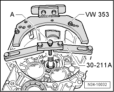
- Secure the Bracket - Multiple Use -30-211A- for the input shaft to the clutch housing.
Note
The clutch housing is shown in the illustration rotated 180º.
- Install the bolt -A- just far enough until the input shaft starts to lift.
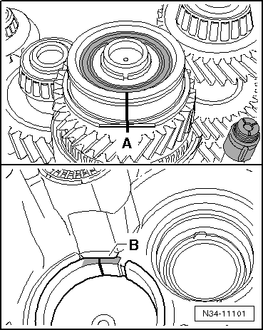
The Grooved Ball Bearing/Input Shaft Only Fits in One Position in the Transmission Housing.
There is a flattened area on the grooved ball bearing and the bearing mount.
The flattened sides -A- on the grooved ball bearing and on the bearing mount -B- must align in the transmission housing.
- Mark this flat side with color.
- Transfer the markings to the upper area of the grooved ball bearing and to the upper area of the transmission housing bearing mount (⇒ next figure).
- Heat the transmission housing in the area near the bearing seat for the grooved ball bearing/input shaft to approximately 100 ºC (212 ºF) for approximately 10 minutes using a Hot Air Blower -VAG1416-, for example.
Note
- It is necessary to heat the transmission housing so that the grooved ball bearing is not damaged when the housing is being installed.
- Apply Sealant evenly onto the sealing surface of the clutch housing.
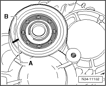
- Align the marking on the grooved ball bearing -A- with the marking on the transmission housing -B- and mount the transmission housing.
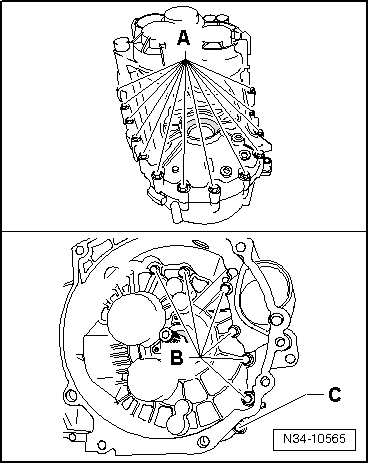
- Install the transmission housing and tighten the new bolts -A through C-.
Transmission with Reinforcement Measures (Manual Transmission 0FB)
Allocate Transmission Using the Code Letters (for Manual Transmission 0FB in CC, Passat and Golf.
For Manual Transmission 0FB in Scirocco.
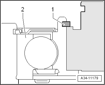
- Redetermine the locking ring -1- for the grooved ball bearing/input shaft -2-:
- Check that the input shaft with the Bracket - Multiple Use -30-211A- is pressed up against the transmission housing.
- Determine the thickest locking ring that has not yet been used and install it in the grooved ball bearing/drive axle, starting with the thickest locking ring.
The following locking rings are available. Refer to the Parts Catalog for allocation.
| Circlip Thickness (mm) | ||
| 2.03 | 2.09 | 2.15 |
| 2.21 | 2.27 | |
Continuation for All
- Install the grooved ball bearing/input shaft locking ring -1-.
- Remove the Bracket - Multiple Use -30-211A- for the input shaft.
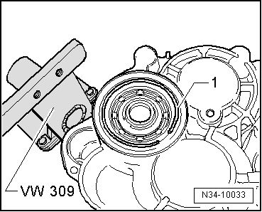
- If the retaining sleeve for the gearshift shaft was removed, then install it now all the way onto the tool.
- Turn the transmission so that the opening for the gearshift shaft faces up in the assembly stand.
Note
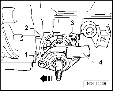
Use the Pry Lever -80-200- to press against the spring force of the securing bushing in direction of -arrow- when installing so that the gearshift shaft -1- does not touch the securing bushing -2- when removing.
- Install the gearshift shaft -1- into the lower bearing -2- and into the shift forks -3-.
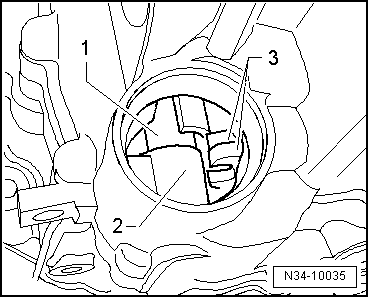
Note
The cover is not shown in the illustration.
- Push the gearshift shaft -1- against the retaining sleeve -2- in direction of -arrow- and guide is through the shift fork all the way down using the shift finger -3-.
- The gearshift cover -4- must stand parallel to the bolting surface on the transmission housing.
- It must be possible to move the gearshift shaft easily (forward and backward).
Note
If the gearshift cover is at an angle to the bolting surface, then the gearshift shaft is not installed into the lower bearing.
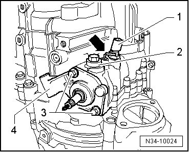
- Tighten the bolts -3- for the gearshift cover -4-.
- Install the locking screw -2-, lock elbow -arrow- must not be installed when doing so.
- Install the Back-Up Lamp Switch -F4--1-.
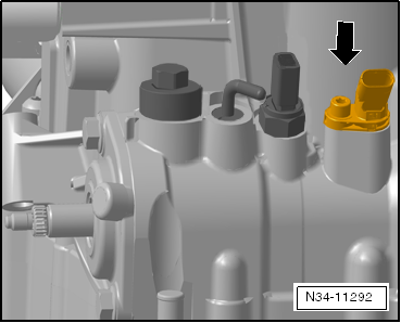
- Transmission on vehicles with Stop/Start system: install the Transmission Neutral Position Sensor -G701--arrow- and tighten the screw.
- Install the input shaft seal so that it is flush.
- Install the clutch slave cylinder with release bearing.
- Move the gearshift lever (selector lever) through all the gears.
- Install the cover as follows:
Cover Differentiation
-I- = metal cover; secured with securing ring -A-.
-II- = plastic cover; without securing ring.
Allocation

| Mounting Area for the Cover | Cap | Installation |
| -Arrow A- = vertical | Made of metal | Refer to → Fig. ""Metal Cover"" |
| -Arrow B- = at an angle | Plastic | Refer to → Fig. ""Plastic Cover"" |
Metal Cover
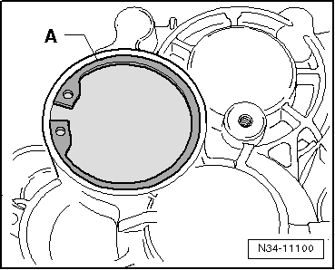
- Install the cap all the way into the transmission housing.
- Secure the cap with the locking ring -A-.
Plastic Cover
- Install the cap all the way into the transmission housing.
Continuation for All
- Always pay attention to the cover allocation.
- Leaks in the case of incorrect installation.
- Allocate the cap. Refer to the Parts Catalog.

- Install the flange shafts with the springs, thrust washers and tapered rings.
AWD Transmission and FWD Transmission with Front Axle Differential Lock
Install the Bevel Box or the Front Axle Differential Lock to the Manual Transmission as Follows:
- Note the transportation of the front axle differential lock.
- Coat the splines on the manual transmission differential with Grease for Clutch Disc Shaft Splines.
Grease allocation. Refer to the Parts Catalog.
- Slide bevel box or flange shaft front axle differential lock completely onto manual transmission. While doing this, join splines of input shaft/bevel box or front axle differential lock centrally with the differential.
- Line up the splines on the right flange shaft with the differential bevel gear. Turn the flange shaft if necessary.
- With proper tooth position and central guiding, the bevel box or front axle differential lock slips up to stop against manual transmission.

Note
Do not pull the bevel box or front axle differential lock with mounting bolts against the manual transmission, otherwise the assembly will tilt and the mounting eyes can break off.
- Tighten the four bolts -arrows- attaching the bevel box or the front axle differential lock to the manual transmission (only three bolts are shown in the illustration).
- Tighten the right flange shaft conical head bolt with the Socket Insert.
Test yourself
A quick Volkswagen Tiguan quiz: every answer comes with an explanation and a link to the manual page.