Output shaft
Assembly overview - Output shaft

Note
- When installing new gear wheels or a new output shaft, observe the technical data and → Electronic Parts Catalog (ETKA).
- Heat gears to max. 120 °C.
- Install all bearings, gear wheels and synchronizer rings on the output shaft with gear oil.
- Replace both tapered roller bearings together.
- Heat bearing inner races/tapered roller bearings to 100 °C before installation.
- Do not mix up the synchronizer rings. When reusing them, always assign them to the original gear wheel.

- Clutch housing
- Different Ø bearing seat for outer race/tapered roller bearing
- Adjusting shim
- Determine thickness
- Outer race/tapered roller bearing
- Pull off
- Differentiation
- Ø bearing seat in clutch housing = 51 mm, press in
- Ø bearing seat in clutch housing = 56 mm, press in
- Inner race/tapered roller bearing
- Ø matched to outer race/tapered roller bearing
- Assignment → Electronic Parts Catalog (ETKA)
- Press off
- Press on
- Output shaft
- adjust
- Stop ring
- prevents the locking pieces from migrating out
- remove
- install
- Sliding sleeve with synchronizer hub for 5th and R gear
- remove after removing snap ring
- disassemble and assemble
- observe installed position and place on shaft
- 5th gear synchronizer ring
- check for wear
- Circlip
- replace after removal
- Needle bearing
- for 5th gear
- 5th gear wheel
- Washer
- holds thrust washers in position on output shaft
- Thrust washers
- for 4th and 5th gear
- 2 pieces
- insert lug of thrust washer into bore of output shaft
- Needle bearing
- for 4th gear
- 4th gear wheel
- Circlip
- replace after removal
- 4th gear synchronizer ring
- check for wear
- Sliding sleeve with synchronizer hub for 3rd and 4th gear
- pull off after removing snap ring
- disassemble
- Assemble sliding sleeve/synchronizer hub and
- Press on
- 3rd gear synchronizer ring
- check for wear
- Circlip
- replace after removal
- Needle bearing
- for 3rd gear
- 3rd gear wheel
- Washer
- holds thrust washers in position on output shaft
- Thrust washers
- for 2nd and 3rd gear
- 2 pieces
- insert lug of thrust washer into bore of output shaft
- Needle bearing
- for 2nd gear
- 2nd gear wheel
- Circlip
- replace after removal
- Synchronizer ring (inner ring for 2nd gear)
- Synchronizer 1st/2nd gear
- Installation position
- outer ring for 2nd gear
- Synchronizer 1st/2nd gear
- Installation position
- 2nd gear synchronizer ring
- Synchronizer 1st/2nd gear
- Installation position
- check for wear
- Sliding sleeve with synchronizer hub for 1st and 2nd gear
- remove after removing snap ring
- disassemble
- Assemble sliding sleeve/synchronizer hub
- Installation position
- 1st gear synchronizer ring
- check for wear
- Circlip
- replace after removal
- Needle bearing
- for 1st gear
- 1st gear wheel
- remove with inner race/tapered roller bearing
- Thrust washer
- for 1st gear
- Inner race/tapered roller bearing
- Press off
- Press on
- Circlip
- replace after removal
- redetermine when replacing tapered roller bearing and output shaft
- Outer race/tapered roller bearing
- Pull off
- Press in
- Transmission housing
Disassemble and assemble output shaft
Required Special Tools, Test and Measuring Equipment and Auxiliary Items
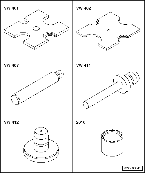
- Pressure plate -VW 401-
- Pressure plate -VW 402-
- Pressure ram -VW 407-
- Pressure ram -VW 411-
- Pressure ram -VW 412-
- Tube section -2010-
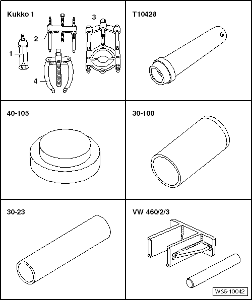
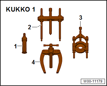
- -1- Internal puller 36...46 mm, e.g. -Kukko 21/6-
- -4- Counter support, e.g. -Kukko 22/2-
- -3-Separator 22...115 mm, e.g. -Kukko 17/2-
- Pressure plate -40 - 105-
- Driving sleeve -30 - 100-
- Attachment -30 - 23-
- Extractor -VW 460/2-
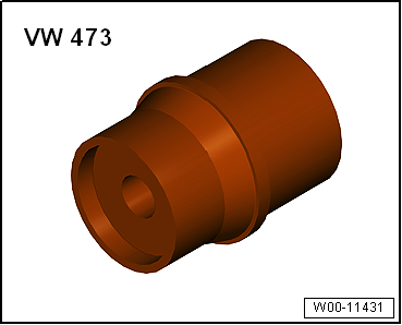
- Pressure piece -T10428- or
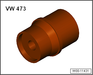
- Pressure piece -VW 473-
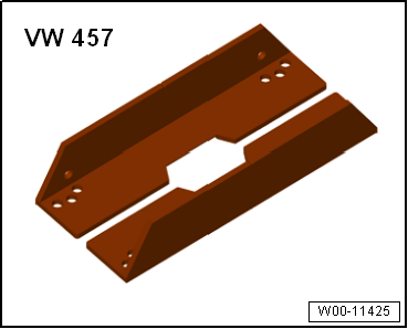
- Support rails -VW 457-
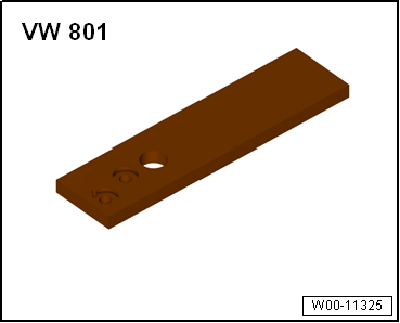
- Holding plate -VW 801-
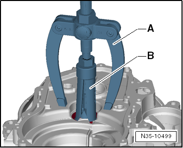
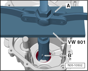
Pull outer race/tapered roller bearing out of clutch housing
- Counter support, e.g. -Kukko 22/2-
- Internal puller 36... 46 mm, e.g. -Kukko 21/6-
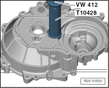
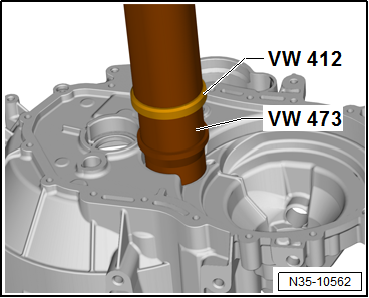
Differentiation of bearing seat for outer race/tapered roller bearing in clutch housing
The Ø of the bearing seat for the outer race/tapered roller bearing is different.
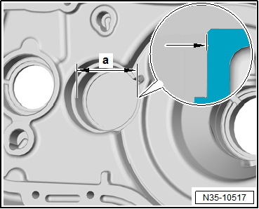

Ø bearing seat = 51 mm, press outer race/tapered roller bearing into clutch housing
Ø bearing seat = 56 mm, press outer race/tapered roller bearing into clutch housing
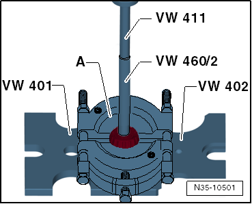
Press off inner race/tapered roller bearing for bearing in clutch housing
- Separator 12... 75 mm, e.g. -Kukko 17/1-
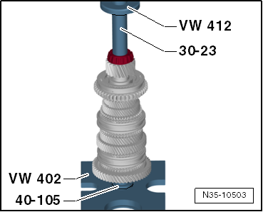
Press on inner race/tapered roller bearing for bearing in clutch housing
Pull outer race/tapered roller bearing out of transmission housing
- Counter support, e.g. -Kukko 22/2-
- Internal puller 36... 46 mm, e.g. -Kukko 21/6-
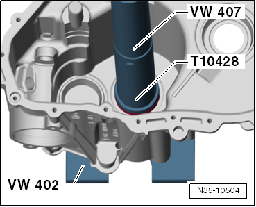
Press outer race/tapered roller bearing into transmission housing
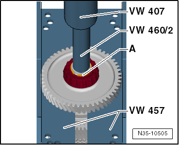
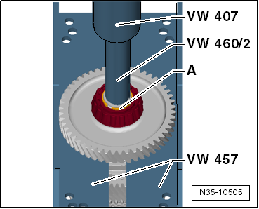
Press off inner race/tapered roller bearing on the side facing the transmission housing, with 1st gear wheel:
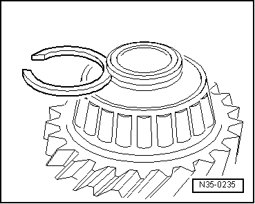
- First remove snap ring -A- for inner race/tapered roller bearing.
- Place support rails -VW 457- under the constant-mesh teeth, not the synchronizer teeth, of 1st gear wheel.
Below the inner race/tapered roller bearing is the thrust washer for 1st gear wheel.
- Observe thrust washer for 1st gear wheel.
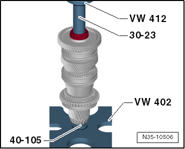
Press on inner race/tapered roller bearing on transmission housing side
- First place 1st gear wheel with thrust washer for 1st gear wheel on.
- Determine snap ring for inner race/tapered roller bearing ⇒ next illustration and install.
Determine snap ring
- Determine and install the thickest snap ring that still fits.
- Determine snap ring according to table. Part number → Electronic Parts Catalog (ETKA)
The following snap rings are available:

Disassemble output shaft
- Remove snap ring -A- for inner race/tapered roller bearing.
- Place support rails -VW 457- under the constant-mesh teeth, not the synchronizer teeth, of 1st gear wheel.
- Press off 1st gear wheel with inner race/tapered roller bearing.
Below the inner race/tapered roller bearing is the thrust washer for 1st gear wheel.
- Remove thrust washer for 1st gear wheel.
- Remove needle bearing for 1st gear wheel.
- Remove 1st gear synchronizer ring.
- Remove snap ring for 1st/2nd gear synchronizer hub.
- Remove sliding sleeve/synchronizer hub for 1st and 2nd gear.
- Remove 2nd gear wheel with 2nd gear synchronizer ring.
- Remove circlip for needle bearing.
- Remove 2nd gear wheel.
- Remove needle bearing for 2nd gear wheel.
- Remove thrust washers for 2nd and 3rd gear with washer.
- Remove 3rd gear wheel.
- Remove synchronizer ring for 3rd gear with needle bearing.
- Remove circlip for sliding sleeve/synchronizer hub for 3rd and 4th gear.
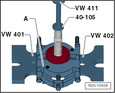
Press off sliding sleeve/synchronizer hub for 3rd and 4th gear together with 4th gear synchronizer ring
- Puller 22... 115 mm, e.g. -Kukko 17/2-
- Position puller -A- under 4th gear synchronizer ring.
- Replace 4th gear synchronizer ring during reassembly.
- Remove 4th gear synchronizer ring.
- Remove 4th gear wheel.
- Remove circlip above needle bearing for 4th gear wheel.
- Remove needle bearing for 4th gear wheel.
- Remove thrust washers for 4th and 5th gear with washer.
- Remove 5th gear wheel.
- Remove needle bearing for 5th gear wheel.
- Remove 5th gear synchronizer ring.
- Remove circlip for sliding sleeve/synchronizer hub for 5th and R gear.
- Remove sliding sleeve/synchronizer hub for 5th and R gear.
Assemble output shaft
Check synchronizer rings for 1st, 3rd - 5th gear for wear
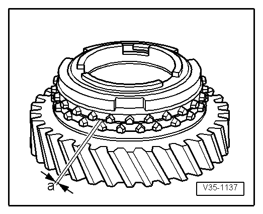
- Press synchronizer ring onto the cone of the gear wheel and measure clearance -a- with a feeler gauge.
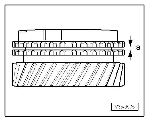

Check synchronizer ring for 2nd gear for wear
- Press synchronizer ring, outer ring and inner ring onto the cone of the gear wheel and measure clearance -a- with a feeler gauge.

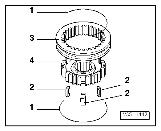
Disassemble and assemble sliding sleeve and synchronizer hub for 1st, 2nd, 3rd and 4th gear
- Spring
- Locking piece
- Sliding sleeve
- Synchronizer hub
- Slide sliding sleeve over the synchronizer hub.
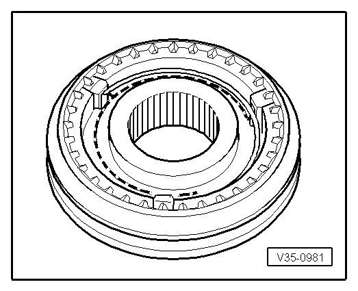
Assembly of sliding sleeve/synchronizer hub for 1st, 2nd, 3rd and 4th gear
Sliding sleeve is slid over the synchronizer hub.
- Install locking pieces and fit springs offset by 120º. The spring must engage with its bent end in the hollow locking piece.
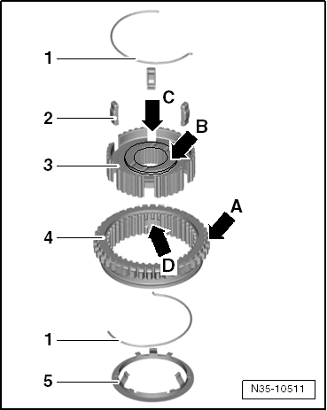
Disassemble and assemble sliding sleeve and synchronizer hub for 5th and R gear
- Spring
- Locking piece
- Synchronizer hub
- Sliding sleeve
- Remove and install stop ring
- Slide sliding sleeve over the synchronizer hub.
- The teeth -arrow A- and the flat collar -arrow B- point in the same direction
- The deeper recesses -arrow C- for locking pieces in the synchronizer hub and the recesses -arrow D- in the sliding sleeve must align.
- Install locking pieces -2- and fit springs -1- offset by 120º.
- The spring must engage with its bent end in the hollow locking piece.
- Install stop ring -5-
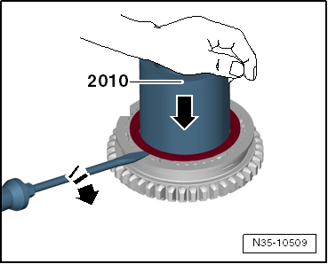
Remove stop ring for locking pieces of sliding sleeve with synchronizer hub for 5th and R gear
- Press tube piece -2010- into the synchronizer hub/stop ring. Alternately pry the stop ring out of the synchronizer hub.
- The stop ring must be fully seated on tube piece -2010-.
- Remove stop ring together with tube piece -2010-.
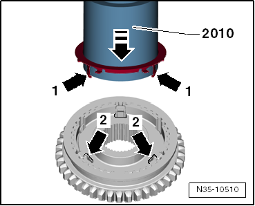
Install stop ring for locking pieces on sliding sleeve with synchronizer hub for 5th and R gear
- Insert stop ring together with tube piece -2010- into synchronizer hub/sliding sleeve for 5th gear.
The 3 lugs -arrow 1- lock into the 3 recesses -arrow 2- for locking pieces of the synchronizer hub. (Only 2 lugs and 2 recesses are shown here.)
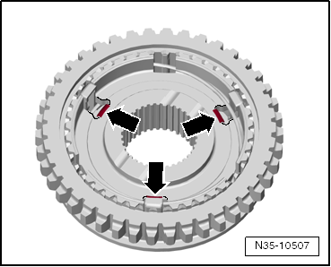
- Remove tube piece -2010-; the lugs -arrows- must engage in the synchronizer hub.
Installation position of sliding sleeve/synchronizer hub for 5th and R gear
- The shift fork groove -arrow 1- points toward the teeth -arrow 2-.
- The stop ring for locking pieces for 5th and R gear is installed.
- Place sliding sleeve/synchronizer hub for 5th and R gear onto the shaft.
- Install circlip.
- Install 5th gear synchronizer ring.
- Place 5th gear wheel with needle bearing onto the shaft.
- Install thrust washers for 4th and 5th gear and.
- Place 4th gear wheel with needle bearing onto the shaft.
- Install circlip.
- Place 4th gear synchronizer ring on.
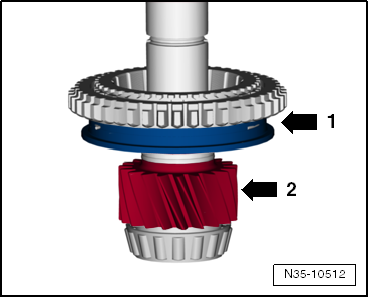
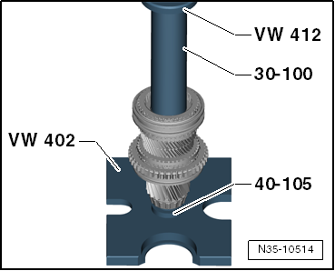
Press on synchronizer hub with sliding sleeve for 3rd and 4th gear
- Install circlip.
- Install 3rd gear synchronizer ring.
- Place 3rd gear wheel with needle bearing onto the shaft.
- Install thrust washers for 2nd and 3rd gear and.
- Place 2nd gear wheel with needle bearing onto the shaft.
- Install circlip.
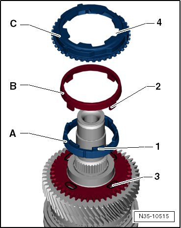
Installation position of outer ring, inner ring and synchronizer ring for 2nd gear
- Place inner ring -A- onto the gear wheel.
- The lugs -1- point away from the gear wheel.
- Place outer ring -B- on.
- The lugs -2- lock into the recesses -3- of the gear wheel.
- Place synchronizer ring -C- on.
- The larger recesses -4- lock onto the lugs -1- of inner ring -A-.
- Place 2nd gear synchronizer ring on.
Installation position of sliding sleeve/synchronizer hub for 1st and 2nd gear
- The chamfer -arrow 1- points away from 2nd gear wheel -arrow 2-.
- Place sliding sleeve/synchronizer hub for 1st and 2nd gear on.
- Install circlip.
- Install 1st gear synchronizer ring.
- Place 1st gear wheel with needle bearing onto the shaft.
- Place thrust washer for 1st gear on.

Note
Press on inner race/tapered roller bearing for mounting in the transmission housing
- Install circlip.

Adjust output shaft

Required Special Tools, Test and Measuring Equipment and Auxiliary Items
- Clamping block -VW 313-
- Gearbox holder -T10484-
- Gauge block plate -VW 385/17-
- Universal dial gauge holder -VW 387-
- Pressure ram -VW 412-
- Pressure piece -T10428- or
- Pressure piece -VW 473-
- -1- Internal puller 36...46 mm, e.g. -Kukko 21/6-
- -4- Counter support, e.g. -Kukko 22/2-
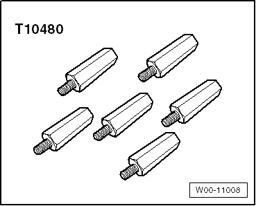
- Adapter -T10480-
- Torque Wrench -V.A.G 1331-
- Dial gauge -VAS 6080A-
- Dial gauge extension 30 mm
(Determining shim for output shaft)
Output shaft readjustment is required if the following components are replaced:
- Transmission housing
- Clutch housing
- Output shaft
- Tapered roller bearing for output shaft
Adjustment overview
Requirement:
- Sealing surfaces of clutch housing and transmission housing must be cleaned of sealant.
- Both bearing inner races for the tapered roller bearings are pressed onto the output shaft.
- The outer race/tapered roller bearing is pressed into the transmission housing.
- Remove reverse idler shaft.
- Press outer race/tapered roller bearing into clutch housing with a 1.40 mm thick shim.
- Install output shaft in transmission housing.
- Install clutch housing and tighten bolts crosswise to specified torque.
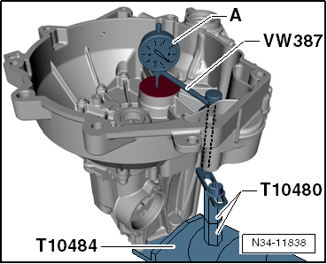
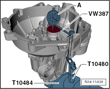
- Install measuring tools.
- Set dial gauge (3 mm measuring range) to "0" with 1 mm preload.
- Loosen clutch housing/transmission housing mounting bolts crosswise until the bolts release the clutch housing or output shaft.
- Do not move clutch housing by hand
- Read and record dial gauge value (example: 0.60 mm).
Determine shim
The specified bearing preload is achieved by subtracting the measured value (0.60 mm) from the installed shim (1.40 mm) and adding a constant preload allowance (0.20 mm).
Example:
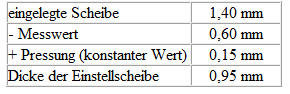
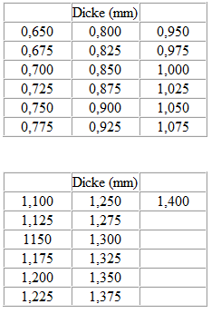
- Determine shim thickness from table.
- Shim part number → Electronic Parts Catalog (ETKA).
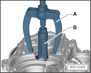
- Remove clutch housing and pull out outer race/tapered roller bearing.
- Counter support, e.g. -Kukko 22/2-
- Internal puller 36... 46 mm, e.g. -Kukko 21/6-
- Remove installed shim (1.40 mm thick) from clutch housing.
Different tolerances allow the required shim thickness to be measured precisely.
If the measured shim thickness is greater than listed in the table, 2 shims matching the measured value can be installed.
Table of adjusting shims
- Press outer race/tapered roller bearing into clutch housing with a 1.40 mm thick shim.
Perform check measurement
- Determined shim installed.
- Install measuring tools.
- Set dial gauge (3 mm measuring range) to "0" with 1 mm preload.
- Loosen clutch housing/transmission housing mounting bolts crosswise until the bolts release the clutch housing or output shaft.
- With the correct shim selected, the dial gauge must now show a value between 0.15 mm and 0.25 mm.
Reverse idler shaft
Removing and installing reverse idler shaft
- Remove clutch housing.
- Remove reverse idler gear with roller bearing and thrust washers.
- Pull reverse idler shaft out of transmission housing with pliers.
Reverse idler shaft will be damaged during removal
- Carefully drive in new reverse idler shaft with a plastic hammer.
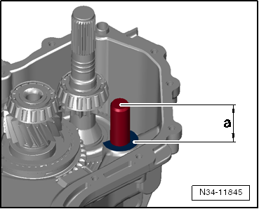
Dimension - a - = 41.5 mm
- Install reverse idler gear, roller bearing and thrust washers.
- Install clutch housing.