Operating and display unit
Overview of operating and display unit
Overview - operating and display unit, from calendar week 22/2012
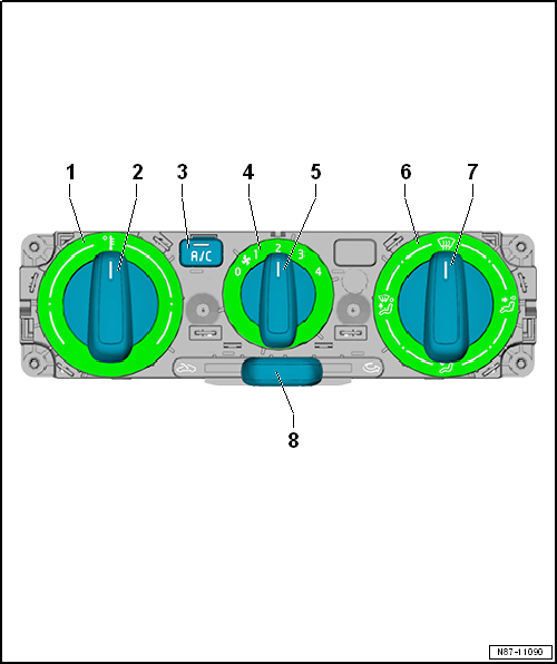
- Temperature Setting Display
- Shows the selected temperature range.
- Temperature Adjustment Rotary Knob
- Left: reduce temperature.
- right: increase temperature.
- A/C button
- Switches on the A/C compressor via the air conditioning compressor magnetic clutch -N25-.
- Blower speed display
- Shows the selected blower speed.
- Rotary knob for adjusting blower speed
- left: decrease blower speed.
- right: increase blower speed.
- Air Distribution Display
- Shows the selected air outlet.
- Air Distribution Adjustment Rotary Knob
- Adjusting air outflow via the corresponding air outlets
- Slide control for fresh air and recirculation mode
- Moving the control fully to the right sets 100 % recirculation mode and prevents contaminated air from entering the interior.
Overview - operating and display unit, up to calendar week 21/2012
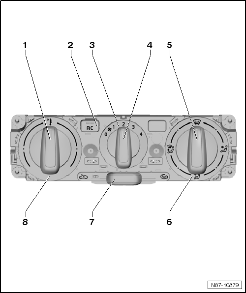
- Temperature Adjustment Rotary Knob
- Left: reduce temperature.
- right: increase temperature.
- A/C button
- Switches on the A/C compressor via the air conditioning compressor magnetic clutch -N25-.
- Blower speed display
- Shows the selected blower speed.
- Rotary knob for adjusting blower speed
- left: decrease blower speed.
- right: increase blower speed.
- Air Distribution Adjustment Rotary Knob
- Adjusting air outflow via the corresponding air outlets
- Air Distribution Display
- Shows the selected air outlet.
- Slide control for fresh air and recirculation mode
- Pressing the control fully to the right sets 100 % recirculation mode and prevents contaminated air from entering the interior.
- Temperature Setting Display
- Shows the selected temperature range.
Removing and Installing Operating and Display Unit
Required Special Tools, Test and Measuring Equipment and Auxiliary Items
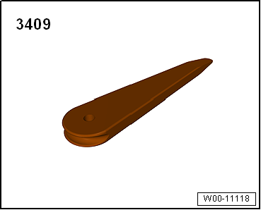
- Release Wedge -3409-
Removing
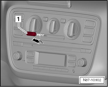
- Remove slide control for fresh air and recirculation mode -1- in direction of arrow.
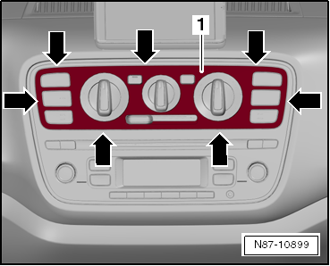
- Unclip cover -1- at the relevant points -arrows- using removal wedge -3409- and remove cover -1-.
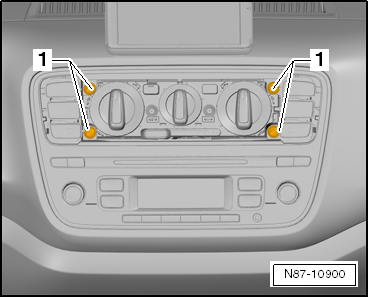
- Unscrew bolts -1- (1.5 N·m).
- Depending on vehicle equipment, remove radio → Communication; or remove centre panel → Body assembly work, interior.
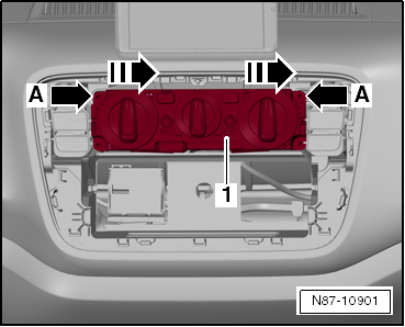
- Unhook operating and display unit -1- from mountings -arrows A- in direction of arrow and pull forward.
- Disconnect electrical connectors on operating and display unit -1-.
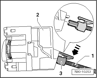
- Disconnect flexible shafts -1- for defrost and air distribution flap, temperature flap and Bowden cable for fresh/recirculation flap from operating and display unit -2-.
- Remove operating and display unit.

Note
The connection of flexible shaft -3- is referred to as the "terminal".
Installing
- Installation is carried out in reverse order, observing the following:
- Always install slide control for fresh air and recirculation mode with plug base facing up.

Note
When fitting the flexible shafts, the actuator units and the rotary knobs for heater air and fresh air regulation must be in a specific position relative to each other, otherwise malfunctions will occur.
Cavity assignment of multiple connectors on rear of operating and display unit
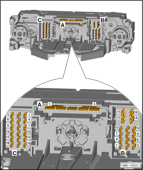
- Blower connector, 5-pin
- Pin assignment can be found in the current wiring diagram → Wiring diagrams, electrical fault finding and component locations.
- Connector, 16-pin
- Pin assignment can be found in the current wiring diagram → Wiring diagrams, electrical fault finding and component locations.
- Connector, 18-pin
- Pin assignment can be found in the current wiring diagram → Wiring diagrams, electrical fault finding and component locations.
Other Control and Regulating Components
Removing and installing outside temperature sensor -G17-
Removing
- Remove front bumper → Body Assembly Work, Exterior.
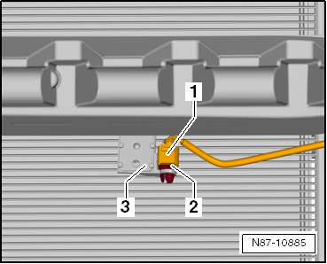
- Disconnect electrical connector -1- from outside temperature sensor -G17- -2-.
- Remove outside temperature sensor -G17- -2- from holder -3-.
Installing
- Installation is carried out in the reverse order.