Check valve timing
Check valve timing, on vehicles without a "TDC mark" on the crankshaft
Required Special Tools, Test and Measuring Equipment and Auxiliary Items
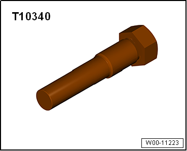
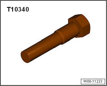
- Locking bolt -T10340-
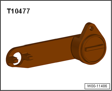
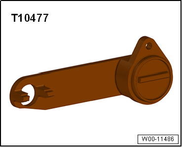
- Camshaft locking tool -T10477-
Test procedure
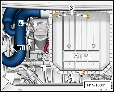
- Disconnect hose -1- from air filter housing.
- Pull air filter housing upward off the bolts at points -2- and -3-.
- Push the air filter housing with the intake connector out of mount -4- in the -arrow direction-.
- Remove the air filter housing from the engine compartment.
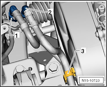
- Unlock and disconnect fuel supply line -1- and vent line -2-.
- Open cable routing -3- and remove hoses.
- Plug lines so that no dirt can enter the fuel system.
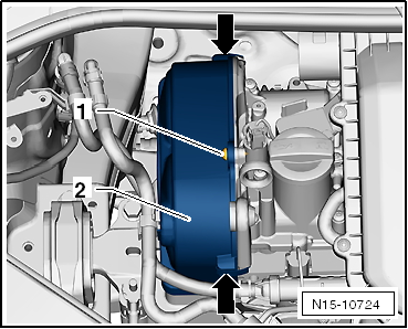
- Unhook clips -arrow-.
- Unscrew mounting bolt -1- and remove cover -2-.
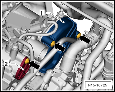
- Unscrew mounting bolts -arrows-.
- Unclip line routing from cover.
- Remove cover -1- and cap -2-.
- Unscrew sealing plug -arrow- from crankcase.
- Lower lift platform fully.

Note
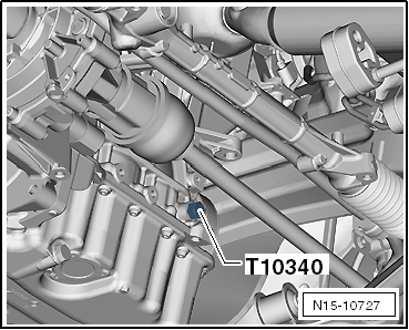
- The lift platform must be lowered fully so that locking bolt -T10340- can be screwed into the crankcase.
- With vehicle raised, the drive shaft is in front of the bore.
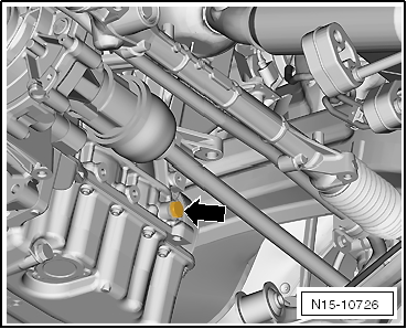
- Screw locking bolt -T10340- into crankcase from above as far as it will go.
- If locking bolt -T10340- cannot be screwed in as far as it will go, the crankshaft is not in the correct position!
- In this case, proceed as described below.
- Unscrew locking bolt.
- Turn crankshaft 90° in direction of engine rotation.
- Turn locking bolt -T10340- into crankcase as far as it will go.
- Tighten locking bolt -T10340- with 30 N·m.
- Turn crankshaft in direction of engine rotation as far as it will go.
The locking bolt -T10340- blocks the crankshaft in the direction of engine rotation.
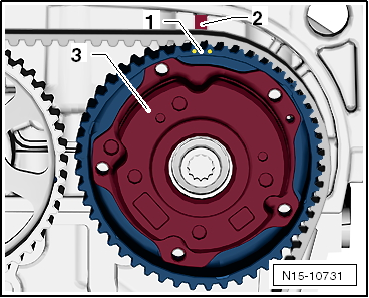
The marked tooth gap -1- of the camshaft adjuster -3- is opposite web -2- on the camshaft housing.
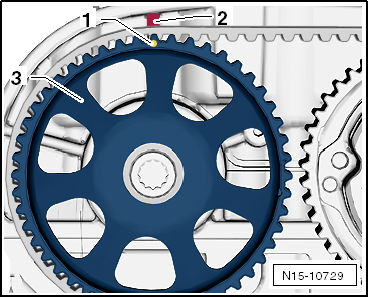
The marked tooth -1- of the exhaust camshaft sprocket -3- is opposite web -2- on the camshaft housing.
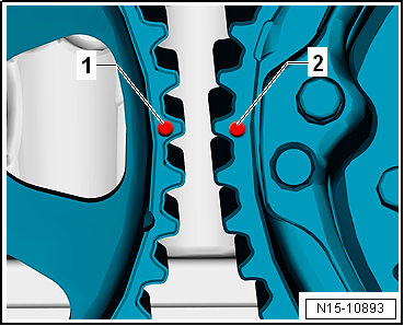
- The additional mark -1- on the exhaust camshaft and the mark -2- on the camshaft adjuster are slightly offset from each other.
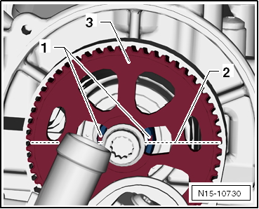
- The slots -1- of the intake camshaft -3- are above the camshaft centerline -2-.
- The slots -1- of the exhaust camshaft are above the camshaft centerline -2-.
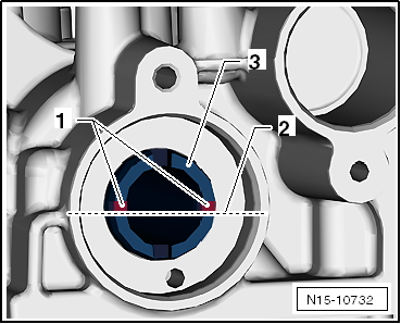
- The cutouts of the gear -3- point slightly upward in the area of the slots.
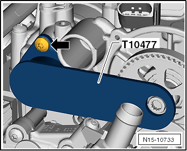
- The camshaft locking tool -T10477- must fit in easily.
- Do not use a impact tool to install the camshaft locking tool!
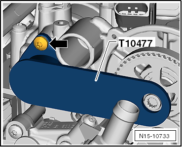
- Insert camshaft locking tool -T10477- into the camshafts as far as it will go and tighten the bolt -arrow- by hand.
If the camshaft locking tool cannot be inserted:
- Set valve timing "Setting valve timing".
If the camshaft locking tool can be inserted:
- Valve timing is OK.
- Reassembly is carried out in the reverse order of removal.
- After completing the work, make sure that locking bolt -T10340- and camshaft locking tool -T10477- have been removed.
Tightening torques
- Attachments camshaft housing "Assembly overview - Cylinder head"
- Tightening torque, crankcase sealing plug: 30 N·m
Check valve timing; on vehicles with "TDC mark" on the crankshaft
Required Special Tools, Test and Measuring Equipment and Auxiliary Items
- Locking bolt -T10340-
- Camshaft locking tool -T10477-
Test procedure
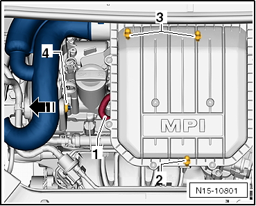
- Disconnect hose -1- from air filter housing.
- Pull air filter housing upward off the bolts at points -2- and -3-.
- Push the air filter housing with the intake connector out of mount -4- in the -arrow direction-.
- Remove the air filter housing from the engine compartment.
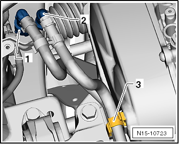
- Unlock and disconnect fuel supply line -1- and vent line -2-.
- Open cable routing -3- and remove hoses.
- Plug lines so that no dirt can enter the fuel system.
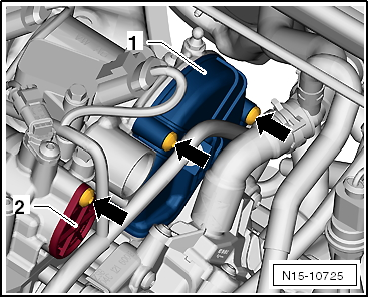
- Unhook clips -arrow-.
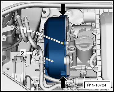
- Unscrew mounting bolt -1- and remove cover -2-.
- Unscrew mounting bolts -arrows-.
- Unclip line routing from cover.
- Remove cover -1- and cap -2-.
Risk of damage to the engine! The "TDC position" must be checked as described!
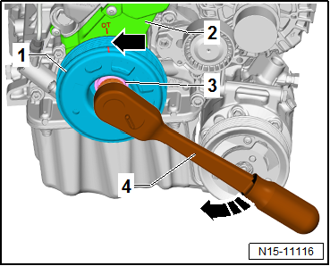
Turn the crankshaft to "TDC" as follows:
- Using ratchet -4- on center bolt -3-, turn the crankshaft in the direction of engine rotation -arrow-.
- The crankshaft is at "TDC position" when the mark -arrow- on vibration damper -1- is aligned with the "TDC mark" on the lower timing belt cover -2-.
Risk of engine damage. If camshaft locking tool -T10494- cannot be inserted as far as it will go, the crankshaft is not in the correct position. Turn the crankshaft further in the direction of engine rotation -arrow direction- until the "TDC mark" is reached again.
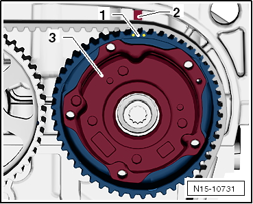
The marked tooth gap -1- of the camshaft adjuster -3- is opposite web -2- on the camshaft housing.
The marked tooth -1- of the exhaust camshaft sprocket -3- is opposite web -2- on the camshaft housing.
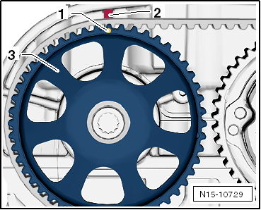
- The additional mark -1- on the exhaust camshaft and the mark -2- on the camshaft adjuster are slightly offset from each other.
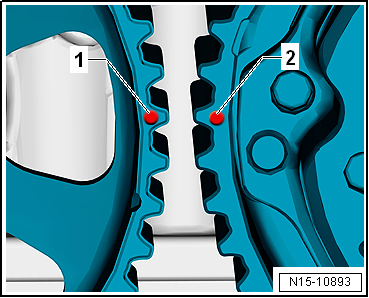
- The slots -1- of the intake camshaft -3- are above the camshaft centerline -2-.
- The slots -1- of the exhaust camshaft are above the camshaft centerline -2-.
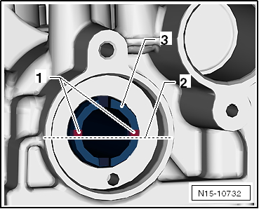
- The cutouts of the gear -3- point slightly upward in the area of the slots.
- The camshaft locking tool -T10477- must fit in easily.
- Do not use a impact tool to install the camshaft locking tool!
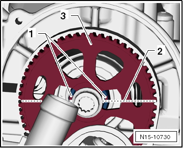
- Insert camshaft locking tool -T10477- into the camshafts as far as it will go and tighten the bolt -arrow- by hand.
If the camshaft locking tool cannot be inserted:
- Set valve timing "Setting valve timing".
If the camshaft locking tool can be inserted:
- Valve timing is OK.
- Reassembly is carried out in the reverse order of removal.
Tightening torques
- Attachments camshaft housing "Assembly overview - Cylinder head"