Steering & Suspension
Suspension Control Arm R&R
In this manual: Steering & Suspension
47steps
~282min
4/5difficulty
Done 0 of 47
Front Suspension
Lower
Removal- Remove front tire and wheel assembly.
- Remove front lower control arm ball stud cotter pin. Discard pin, Fig. 1.
- Loosen front lower control arm ball stud nut until nut is level with top of ball stud.
- Separate front lower control arm from steering knuckle, using separator tool No. J-43828, or equivalent.
- Remove front lower control arm ball stud nut, Fig. 2.
- Remove front lower control arm front nut and bolt. Discard nut and bolt, Fig. 3.
- Remove front lower control arm rear nuts and bolts, Fig. 4.
- Remove front lower control arm from vehicle, Fig. 4.
- Transfer components, as required.
- Position front lower control arm on vehicle.
- Install front lower control arm rear bolts and nuts and torque nuts to 52 ft. lbs.
- Install NEW front lower control arm front bolt and NEW nut and tighten nut on first pass to 85 ft. lbs., second pass turn an additional 90° and final pass to 15°.
- Install front lower control arm ball stud nut and tighten. Torque nut to 89 inch lbs., and turn an additional 165°.
- Install a NEW front lower control arm ball stud cotter pin.
- Install front tire and wheel assembly.
- Measure and adjust wheel alignment.
Rear Suspension
Upper Arm
Rear brake hose bracket must be installed on side of upper control arm bracket closest to front of vehicle. Rear brake hose bracket must be installed parallel to upper control arm.Head of rear brake hose bracket must be installed facing rear of vehicle.
|
Lower Arm
|
Adjust Link
- Raise vehicle.
- Remove rear wheel and tire assembly.
- Remove adjustment link to knuckle bolt (1) and nut, Fig. 11.
- Remove adjustment link to support bolt (2) and nut, Fig. 11.
- Remove adjustment link.
- Inspect rear alignment.
- Reverse procedure to install. Torque adjust link bolts and nuts to 118 ft. lbs.
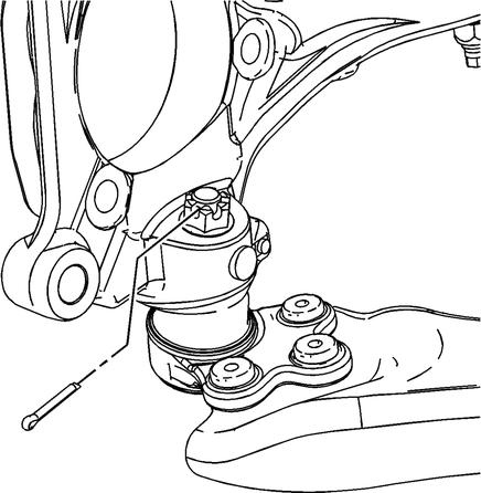
Fig. 1
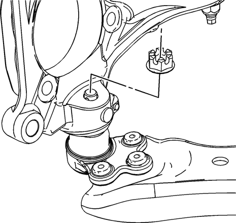
Fig. 2
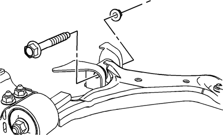
Fig. 3
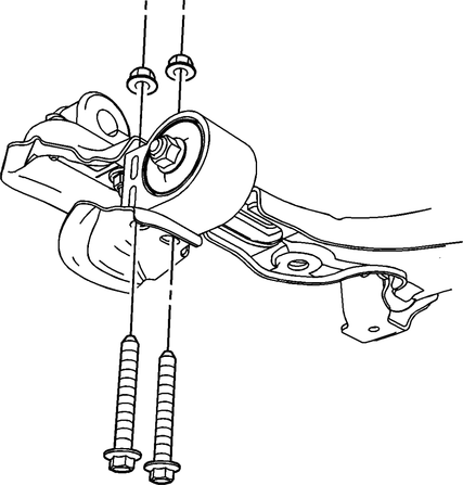
Fig. 4
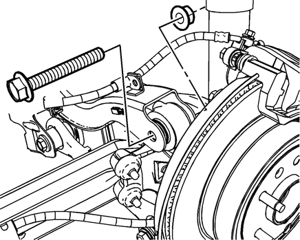
Fig. 5
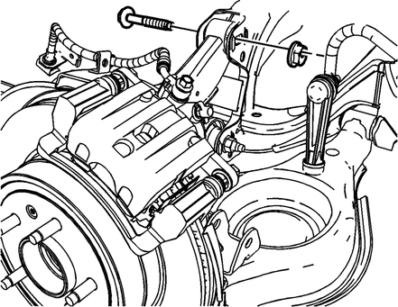
Fig. 6
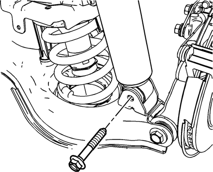
Fig. 7
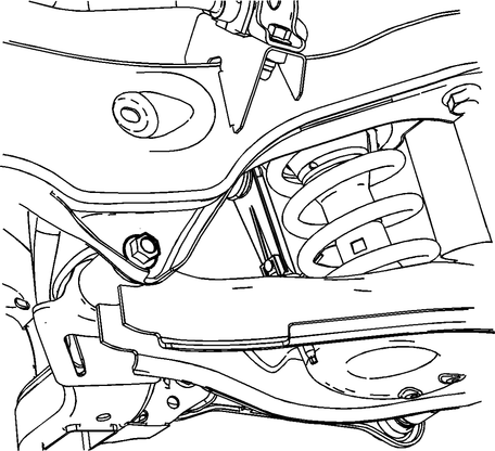
Fig. 8
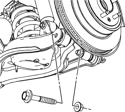
Fig. 9
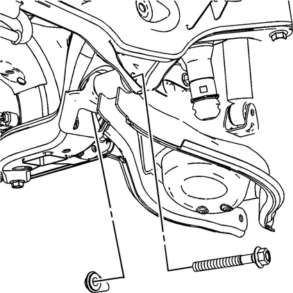
Fig. 10
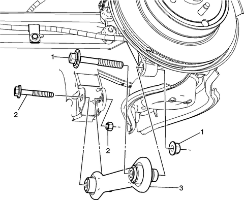
Fig. 11
Chevrolet Captiva is covering essential aspects of the vehicle's suspension system, including the Front Suspension, Rear Suspension, and Adjusting the Linkages. The manual delves into the Front Suspension, detailing components such as front struts, control arms, bushings, ball joints, and steering components. It provides instructions for inspecting these parts, servicing or replacing them as needed, and includes torque specifications and alignment procedures to maintain proper suspension function and vehicle handling. Proper maintenance of the front suspension ensures optimal ride comfort, stability, and safety for the vehicle. Similarly, information about the Chevrolet Rear Suspension system is included in the manual. This section covers rear shocks, control arms, bushings, and sway bars. The manual guides users through inspecting, servicing, and replacing rear suspension components, as well as procedures for adjusting rear wheel alignment. Proper rear suspension maintenance contributes to vehicle stability, handling, and overall ride quality. The manual also addresses Adjusting the Linkages within the suspension system. This involves fine-tuning components such as sway bar links, tie rods, and control arm linkages to optimize suspension geometry, stability, and steering responsiveness.Properly adjusted linkages are crucial for maintaining vehicle safety, precise handling, and smooth driving experience.
Test yourself
A quick Chevrolet Captiva quiz: every answer comes with an explanation and a link to the manual page.
Was this page helpful?