General
Communication between the vehicle's various control units is carried out over multiplexed networks. There are four networks. Multiplexing consists of carrying over a two-wire network:
- operating commands,
- status information,
- digital sensor data for the various control units.
The control units drive the power outputs. Interrogating the control units with the diagnostic tool allows faults stored in their memory to be detected. The BSI is the hub of the communication network. It is the interface between the VAN and CAN networks. The BSI is the control unit that provides the link with the diagnostic tool. The BSI also manages a load shedding and load restoration strategy.
The network names are:
- CAN network,
- VAN BODY 1 network,
- VAN BODY 2 network,
- VAN COMFORT network.
Two configurations can be set by coding the BSI:
- customer configuration,
- factory configuration is used on production lines so as not to discharge the vehicle battery.
To save battery energy, two operating modes of the electrical network are possible:
- normal mode,
- economy mode: some electrical functions are deactivated.
In customer configuration, the BSI manages the switch from normal mode to economy mode.
In factory configuration, economy mode is activated by default. Normal mode can be forced by coding.
Also, to reduce power consumption when the engine is not running, the control units can be put into standby. Standby and wake-up of the control units are managed by the BSI.
NETWORK ARCHITECTURE OVERVIEW
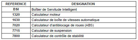
CAN (Controller Area Network) architecture
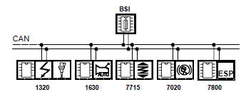
CAN (Controller Area Network) architecture
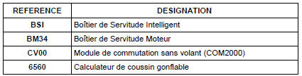
VAN (Vehicle Area Network) Body 1 (safety) architecture
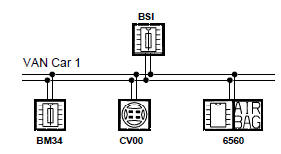
VAN (Vehicle Area Network) Body 1 (safety) architecture
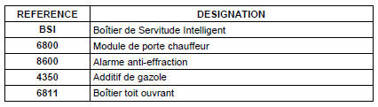
VAN Body 2 architecture
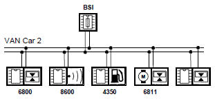
VAN Body 2 architecture
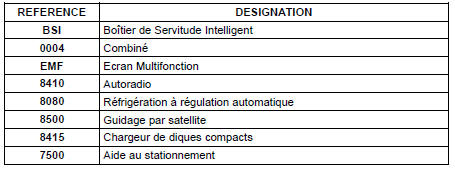
VAN Comfort architecture
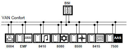
VAN Comfort architecture
Test yourself
A quick Citroen C5 Aircross quiz: every answer comes with an explanation and a link to the manual page.