Driven and Pressure Plates, Clutch Release
GENERAL INFORMATION
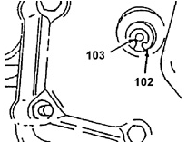
Transmission Input Shaft Snap Ring
102. SNAP RING.
103. BOLT
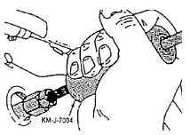
Transmission Input Shaft Removal

Installation of Clamps to Hold Pressure Plate Position
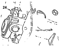
Clutch Fork Bolt
24. BOLT
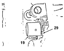
Release Bearing Guide Sleeve Bolt Attachment
19. Release bearing guide sleeve.
29. Bolt.
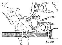
Clutch Shaft Bushing Removal
Remove or disconnect:
Must be used.
– 17 mm transmission case plug puller.
– KM-323 Slotted Wrench.
– KM-552 Bracket.
– KM-J-7004 Installation Tool.
– KM-526A Clamp Set.
– KM-304 Installation Shaft.
– installation tool for the input shaft seal.
PROCEDURE.
1. Disconnect the negative battery cable.
2. Measure the free length of the threaded cable end. Record the result.
measuring tools for use during installation and preliminary adjustment.
new cable.
3. Disconnect the cable end 3 from the clutch release shaft lever 1.
3a. Remove clip 2.
3b. Unscrew the nut 4.
4. Raise the vehicle and support it properly.
5. Splash shield.
6. Left front wheel.
7. Plug from the transmission case using the 17 mm puller.
8. Snap ring 102 securing the input shaft.
104. Before removal.
mark the relative position of the input shaft and the gear cluster with paint.
9. Unscrew bolt 103 from the input shaft using the KM slotted wrench.
323..
10. Install the puller into the input shaft bore. Using the installation tool
KM-J-7004, remove the input shaft from the gear cluster.
11. Remove oil pan 15 by unscrewing the bolts.
16..
12. Press the clutch release lever and install one of the clamps from the KM-526A set into the window of clutch housing 26.
12a. Rotate the flywheel 120 degrees and install the second clamp.
12b. Rotate the flywheel 120 degrees and install the third clamp.
Warning.
The pressure plate and driven disc cannot be removed without first.
installing three clamps (see figure, Cable-Operated Clutch).
13. Unscrew bolts 28 securing the clutch housing to the flywheel and remove washers 27. Support the clutch housing while removing the last bolt.
14. Clutch housing 26 and driven disc
25..
15. Unscrew fork bolt 24 and remove the washer.
23..
16. Remove shaft 1 upward from the transmission case.
17. Fork 21 and release bearing 20 from guide sleeve 19.
18. Guide sleeve 19 by unscrewing the bolts.
29..
18a. Input shaft seal 17 from guide sleeve 19.
18b. O-ring 18 from the groove in the transmission case.
19. Clutch shaft bushings 22. Use installation shaft KM-
304..
Install or connect
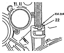
Clutch Shaft Bushing Installation
22. SHAFT BUSHING

Input Shaft Seal Installation
19. RELEASE BEARING GUIDE SLEEVE
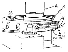
Installing KM-526A Clamps on the Clutch Housing A. PRESS
26. CLUTCH HOUSING

Clutch Housing and Flywheel Alignment Marks A. ALIGNMENT MARKS OF CLUTCH HOUSING AND FLYWHEEL.
26. CLUTCH HOUSING
101. FLYWHEEL

Installing Driven Disc Coaxial to Input Shaft
25. CLUTCH HOUSING
104. INPUT SHAFT
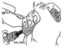
Installing Input Shaft into Gear Cluster
PROCEDURE.
1. Clutch shaft bushings 22. Use installation shaft KM-
304. After installation, lubricate the bushings with grease part number 1052349 or
equivalent.
2. Install input shaft seal 17 into guide sleeve 19.
19. Use
installation tool and a hammer.
3. Install O-ring 18 onto guide bushing 19 and secure bushing 19.
with bolts 29 to the housing. Tighten the guide bushing bolts to torque 5 N·m..
4. Lubricate the surface of the guide sleeve with a thin layer of grease part number 1052349 or equivalent.
5. Lubricate the release bearing bore with a thin layer of grease part number 1052349 or equivalent.
6. Install release bearing 20 with fork 21 onto the guide sleeve.
19..
7. Insert the shaft from above.
1..
7a. Pass the shaft through the fork bore.
21..
7b. Align the fork with the shaft and secure it with bolt 24 and washer 23. Tighten the fork bolt to 35 N·m.
8. Place new clutch housing 26 in the press.
8a. Press the diaphragm spring fingers with the press and install.
Evenly around the periphery of the cover, install three clamps from kit KM-526A.
9. Install clutch cover 26 with driven disc 25 onto the flywheel. The extended hub of the driven disc must face the transmission case.
9a. Apply a thin layer of grease to the driven disc splines. Use grease
part number 1052349 or equivalent.
9b. Align the marks on the flywheel and the clutch cover.
9c. Install two bolts 28 with washers into the flywheel.
27..
9d. Tighten the clutch cover bolts to 15 N·m.
9e. Install the driven disc coaxially with the splined end of the input shaft.
The input shaft must be installed in the gear cluster in its original
marks.
10. Install the remaining bolts 28 with washers into the flywheel.
27. Tighten the clutch cover bolts to 15 N·m.
11. Install the input shaft into the gear cluster bore. Use installation tool KM-J-
7004..
12. Install bolt 103 using wrench KM-323. Tighten the input shaft bolt.
to 15 N·m..
13. Install snap ring 102 on the input shaft. The sharp edge of the ring must face the case cover.
14. Remove the case cover plug using a puller. Before installation, apply Teflon thread sealant for pipe connections to the threads. Tighten the cover plug.
Tighten the case cover plug to torque 50 N·m.
15. Remove the three clamps from kit KM-526A from the cover.
16. Install clutch pan 15 and secure it with bolts
16. Tighten the clutch pan bolts.
to 7 N·m..
17. Dust shield.
18. Left front wheel.
19. Lower the vehicle.
20. Connect cable end 3 to the shaft lever.
1..
21. Screw nut 4 onto the threaded cable end to the position it occupied before
disassembly.
22. Adjust the clutch cable.
23. Clip.
2..
24. Negative battery cable.
Test yourself
A quick Daewoo Nexia quiz: every answer comes with an explanation and a link to the manual page.