Evaporative Emissions
The vehicle emission vacuum routing diagrams are contained in the Description and Operation subsection of the Engine Emissions Control section. Refer to Section 303-08.
The Evaporative Emission (EVAP) system consists of the:
- EVAP canister purge valve.
- EVAP canister.
- EVAP canister vent solenoid.
- fuel vapor tube assembly (includes theFuel Tank Pressure (FTP) sensor).
- fuel tank filler cap.
The EVAP system:
- is equipped with an On-Board Refueling Vapor Recovery (ORVR) system.
- prevents hydrocarbon emissions from reaching the atmosphere.
- stores fuel vapors in the EVAP canister that are generated during vehicle operation hot soak or vehicle refueling, until they can be consumed by the engine during normal engine operation.
- routes the stored fuel vapors to the engine during engine operation.
- is controlled by the PCM which, using various sensor inputs, calculates the desired amount of EVAP purge flow. The PCM regulates the purge flow, induced by the application of intake manifold vacuum, by varying the current applied to the canister purge valve.
The fuel vapors are routed:
- from the fuel tank through the fill limit valve and fuel vapor vent valve.
- to the EVAP canister through a vapor tube.
- to the engine when the EVAP canister purge valve is opened by the PCM.
The EVAP canister:
NOTE:The EVAP canister on a Partial Zero Emissions Vehicle (PZEV) is similar in appearance, but unique in design and is not interchangeable with a non-PZEV canister.
- is located under the rear of the vehicle.
- contains activated carbon.
- stores fuel vapors.
The fuel tank filler cap:
- relieves system vacuum.
The EVAP canister vent solenoid:
- is normally open.
- seals the EVAP system for the inspection and maintenance (I/M 240) test and OBD II leak and pressure tests.
- is mounted internally to the EVAP canister.
- is serviced as a separate item.
The EVAP canister purge valve:
- is normally closed.
- regulates the purging of the EVAP canister.
- is controlled by the PCM.
The FTP sensor (part of the fuel vapor tube assembly):
- monitors the pressure levels in the vapor tube at the fuel tank vapor outlet.
- communicates the pressure reading to the PCM during the OBD II leak test.
- is located in and is serviced as part of the fuel vapor tube assembly.
The EVAP system monitor:
- is a self-test strategy within the PCM which tests the integrity of the EVAP system.
- monitors the EVAP system for leaks.
- monitors electronic EVAP components for irrationally high or low voltages.
- monitors for correct EVAP system operation.
- uses negative and positive leak test methods to test and activate the EVAP system.
The engine ON EVAP leak-check monitor:
- is executed by the individual components of the enhanced EVAP system. Intake manifold vacuum is utilized to reach a target vacuum on the EVAP system. The FTP sensor is used by the engine ON EVAP leak-check monitor to determine if the target vacuum necessary to carry out the leak-check on the EVAP system has been reached. Once target vacuum on the EVAP system is achieved, the change in EVAP system vacuum over a calibrated period of time determines if a leak exists.
The Engine Off Natural Vacuum (EONV) EVAP leak-check monitor is executed:
- once the engine ON EVAP leak-check monitor is completed and the key is turned OFF. The EONV EVAP leak-check monitor determines if a leak is present when the naturally occurring change in the fuel tank pressure or vacuum does not exceed a calibrated limit during a calibrated amount of time. A separate, low-power consuming microprocessor in the PCM manages the EONV leak-check. The engine OFF EVAP leak-check monitor is executed by the individual components of the enhanced EVAP system.
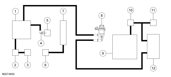
| Item | Part Number | Description |
|---|---|---|
| 1 | 9424 | Intake manifold |
| 2 | 9J559 | Swirl control valve solenoid |
| 3 | 9L492 | Swirl control valve actuator |
| 4 | — | PCV valve (part of 6A785) |
| 5 | 6A785 | Crankcase vent oil separator |
| 6 | 9E652 | Air Cleaner (ACL) outlet pipe |
| 7 | 6582 | Valve cover |
| 8 | 9G641 | Evaporative Emission (EVAP) canister purge valve |
| 9 | 9002 | Fuel tank |
| 10 | — | Fuel Tank Pressure (FTP) sensor (part of 9K164) |
| 11 | 9034 | Fuel tank filler pipe |
| 12 | 9E857 | EVAP canister |
Non PZEV
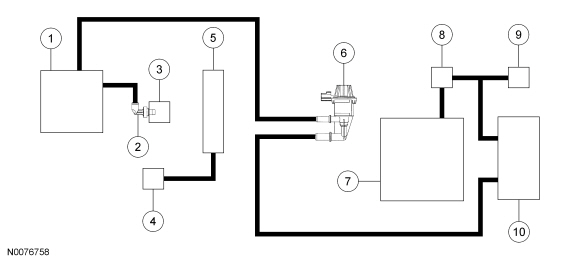
| Item | Part Number | Description |
|---|---|---|
| 1 | 9424 | Intake manifold |
| 2 | — | PCV valve (part of 6A785) |
| 3 | 6A785 | Crankcase vent oil separator |
| 4 | 9E652 | Air Cleaner (ACL) outlet pipe |
| 5 | 6582 | Valve cover |
| 6 | 9G641 | Evaporative Emission (EVAP) canister purge valve |
| 7 | 9002 | Fuel tank |
| 8 | — | Fuel Tank Pressure (FTP) sensor (part of 9K164) |
| 9 | 9034 | Fuel tank filler pipe |
| 10 | 9E857 | EVAP canister |
Test yourself
A quick Ford Focus quiz: every answer comes with an explanation and a link to the manual page.