The diagnosis in this manual assumes a certain level of skill and knowledge of Ford-approved diagnostic procedures. REFER TO: Diagnostic Methods (100-00 General Information, Description and Operation).
DDM Diagnostic Trouble Code Chart
Trouble Code
Description
Action
B1C03:23
Memory Switch No. 1: Low Signal
GO to Pinpoint Test G
B1C04:23
Memory Switch No. 2: Low Signal
GO to Pinpoint Test G
All Other Diagnostic Trouble Codes (DTCs)
-
REFER TO: Locks, Latches and Entry Systems (501-14 Handles, Locks, Latches and Entry Systems, Diagnosis and Testing).
DTC Chart: DSM
The diagnosis in this manual assumes a certain level of skill and knowledge of Ford-approved diagnostic procedures. REFER TO: Diagnostic Methods (100-00 General Information, Description and Operation).
DSM DTC Chart
Trouble Code
Description
Action
B1298:24
Steering Column Tilt Up Switch: Signal Stuck High
Refer to: Steering Column (211-04 Steering Column, Diagnosis and Testing).
B1299:24
Steering Column Tilt Down Switch: Signal Stuck High
Refer to: Steering Column (211-04 Steering Column, Diagnosis and Testing).
B12A1:24
Steering Column Adjustment Switch: Signal Stuck High
Refer to: Steering Column (211-04 Steering Column, Diagnosis and Testing).
B12A2:24
Steering Column Adjustment Switch: Signal Stuck High
Refer to: Steering Column (211-04 Steering Column, Diagnosis and Testing).
B12A7:11
Steering Column Tilt Sensor A: Short to Ground
Refer to: Steering Column (211-04 Steering Column, Diagnosis and Testing).
B12A7:12
Steering Column Tilt Sensor A: Short to Battery
Refer to: Steering Column (211-04 Steering Column, Diagnosis and Testing).
B12A8:11
Steering Column Telescope Sensor A: Short to Ground
Refer to: Steering Column (211-04 Steering Column, Diagnosis and Testing).
B12A8:12
Steering Column Telescope Sensor A: Short to Battery
Refer to: Steering Column (211-04 Steering Column, Diagnosis and Testing).
B1375:09
Steering Column Tilt Motor: Component Failure
Refer to: Steering Column (211-04 Steering Column, Diagnosis and Testing).
B1375:11
Steering Column Tilt Motor: Short to Ground
Refer to: Steering Column (211-04 Steering Column, Diagnosis and Testing).
B1375:12
Steering Column Tilt Motor: Short to Battery
Refer to: Steering Column (211-04 Steering Column, Diagnosis and Testing).
B1375:13
Steering Column Tilt Motor: Open Circuit
Refer to: Steering Column (211-04 Steering Column, Diagnosis and Testing).
Refer to: Steering Column (211-04 Steering Column, Diagnosis and Testing).
B137E:31
Steering Column Telescope Motor: No Signal
Refer to: Steering Column (211-04 Steering Column, Diagnosis and Testing).
B14C3:24
Rear Seat Height Down Switch: Stuck High Signal
GO to Pinpoint Test F
B14C4:24
Rear Seat Height Up Switch: Stuck High Signal
GO to Pinpoint Test F
B14CB:11
Rear Seat Height Feedback: Short to Ground
GO to Pinpoint Test G
B14KB: 12
Rear Seat Height Feedback: Short to Battery
GO to Pinpoint Test G
B14CE:09
Driver's Seat Power Recliner Motor: Component Failure
GO to Pinpoint Test F
B14CE:11
Horizontal Seat Motor Output: Short to Ground
GO to Pinpoint Test F
B14CE:12
Horizontal Seat Motor Output: Short to Battery
GO to Pinpoint Test F
B14CE:14
Horizontal Seat Motor Output: Short to Ground or Open
GO to Pinpoint Test F
B14CE:15
Horizontal Seat Motor Output: Short to Battery or Open
GO to Pinpoint Test F
B14CE:1A
Horizontal Seat Motor Output: Circuit Resistance Below Threshold
GO to Pinpoint Test F
B14CE:31
Horizontal Seat Motor Power: No Signal
GO to Pinpoint Test G
B14CF:09
Recline Seat Motor Output Signal: Component Failure
GO to Pinpoint Test F
B14CF:11
Recline Seat Motor Output: Short to Ground
GO to Pinpoint Test F
B14CF:12
Recline Seat Motor Output: Short to Battery
GO to Pinpoint Test F
B14CF:14
Recline Seat Motor Output: Short to Ground or Open
GO to Pinpoint Test F
B14CF:15
Recline Seat Motor Output: Short to Battery or Open
GO to Pinpoint Test F
B14CF:1A
Recline Seat Motor Output Signal: Circuit Resistance Below Threshold
GO to Pinpoint Test F
B14CF:31
Recline Seat Motor Output Signal: No Signal
GO to Pinpoint Test G
B14D0:09
Front/Recline Seat Height Motor Power: Component Failure
GO to Pinpoint Test F
B14D0:11
Seat Height/Recline Motor Output Signal: Short to Ground
GO to Pinpoint Test F
B14D0:12
Seat Height/Recline Motor Output Signal: Short to Battery
GO to Pinpoint Test F
B14D0:14
Seat Height/Recline Motor Output Signal: Short to Ground or Open
GO to Pinpoint Test F
B14D0:15
Seat Height/Recline Motor Output Signal: Short to Battery or Open
GO to Pinpoint Test F
B14D0:1A
Front Seat Height/Recline Motor Output Signal: Circuit Resistance Below Threshold
GO to Pinpoint Test F
B14D0:31
Front Seat Height/Recline Motor Output Signal: No Signal
GO to Pinpoint Test G
B14D2:09
Rear Seat Height Motor Power: Component Failure
GO to Pinpoint Test F
B14D2:11
Rear Seat Height Motor Output: Short to Ground
GO to Pinpoint Test F
B14D2:12
Rear Seat Height Motor Output: Short to Battery
GO to Pinpoint Test F
B14D2:14
Rear Seat Height Motor Output: Short to Ground or Open
GO to Pinpoint Test F
B14D2:15
Rear Seat Height Motor Output: Short to Battery or Open
GO to Pinpoint Test F
B14D2:1A
Rear Seat Height Motor Power: Circuit Resistance Below Threshold
GO to Pinpoint Test F
B14D2:31
Rear Seat Height Motor Power: No Signal
GO to Pinpoint Test G
B1B89:11
Seat Slide Motor Speed/Position Sensor: Short to Ground
GO to Pinpoint Test G
B1B89:12
Seat Slide Motor Speed/Position Sensor: Short to Battery
GO to Pinpoint Test G
B1B91:11
Recline Seat Motor Speed/Position Sensor: Short to Ground
GO to Pinpoint Test G
B1B91:12
Recline Seat Motor Speed/Position Sensor: Short to Battery
GO to Pinpoint Test G
B1B93:11
Recline Seat Motor Speed/Position Sensor: Short to Ground
GO to Pinpoint Test G
B1B93:12
Recline Seat Motor Speed/Position Sensor: Short to Battery
GO to Pinpoint Test G
B1B96:24
Seat Slide Forward Switch: High Signal
GO to Pinpoint Test F
B1B97:24
Seat Slide Rearward Switch: Stuck High Signal
GO to Pinpoint Test F
B1B98:24
Seat Recline Up Switch: Stuck High Signal
GO to Pinpoint Test F
B1B99:24
Seat Tilt Down Switch: Signal Constantly High
GO to Pinpoint Test F
B1C00:24
Seat Recline Up Switch: Stuck High Signal
GO to Pinpoint Test F
B1C01:24
Seat Tilt Down Switch: Signal Constantly High
GO to Pinpoint Test F
U0100:00
Lost Communication With ECM/PCM "A": No Sub Type Information
GO to Pinpoint Test V
U0140:00
Lost Communication With Body Control Module: No Sub Type Information
GO to Pinpoint Test L
U0212:00
Lost Communication with Steering Column Control Module: No Sub Type Information
GO to Pinpoint Test Y
U1000:00
Solid State Driver Protection Active - Driver Disabled: No Sub Type Information
FIRST, CHECK for any other related DSM diagnostic trouble codes (DTCs). CLEAR the DTCs. REPEAT the self-test. If DTC U1000:00 returns, INSTALL a new DSM. REFER TO: Driver Front Seat Module (DSM) (501-10A Front Seats, Removal and Installation).
U2100:00
Initial Configuration Not Complete: No Sub Type Information
Using the diagnostic scan tool, PERFORM a PMI on the DSM. REPEAT the self-test and CHECK for a successful PMI. CLEAR the diagnostic trouble codes (DTCs).
U3000:49
Control Module: Internal Electronic Failure
INSTALL a new DSM. REFER TO: Driver Seat Module (DSM) (501-10A Front Seats, Removal and Installation).
DTC Chart: FCIM
The diagnosis in this manual assumes a certain level of skill and knowledge of Ford-approved diagnostic procedures. REFER TO: Diagnostic Methods (100-00 General Information, Description and Operation).
FCIM Diagnostic Trouble Code Chart
Trouble Code
Description
Action
B1034:11
Front Left Seat Heater Element: Short to Ground
GO to Pinpoint Test J
B1034:12
Front Left Seat Heater Element: Short to Battery
GO to Pinpoint Test J
B1034:13
Front Left Seat Heater Element: Open Circuit
GO to Pinpoint Test J
B1036:11
Front Right Seat Heater Element: Short to Ground
GO to Pinpoint Test K
B1036:12
Front Right Seat Heater Element: Short to Battery
GO to Pinpoint Test K
B1036:13
Front Right Seat Heater Element: Open Circuit
GO to Pinpoint Test K
B1038:11
Front Left Seat Heater Sensor: Short to Ground
GO to Pinpoint Test J
B1038:15
Front Left Seat Heater Sensor: Short to Battery or Open Circuit
GO to Pinpoint Test J
B103A: 11
Front Right Seat Heater Sensor: Short to Ground
GO to Pinpoint Test K
B103A: 15
Front Right Seat Heater Sensor: Short to Battery or Open Circuit
GO to Pinpoint Test K
All Other Diagnostic Trouble Codes (DTCs)
-
For the procedure, refer to the appropriate section in Group 415.
DTC Chart: SCME
The diagnosis in this manual assumes a certain level of skill and knowledge of Ford-approved diagnostic procedures. REFER TO: Diagnostic Methods (100-00 General Information, Description and Operation).
SCME Diagnostic Trouble Code Chart
Trouble Code
Description
Action
B1151:4B
Passenger Seat Cushion: Overheated
GO to Pinpoint Test P
B1152:4B
Passenger Seatback: Overheating
GO to Pinpoint Test Q
B1153:4B
Driver Seat Cushion: Overheated
GO to Pinpoint Test N
B1154:4B
Driver Seatback: Overheating
GO TO Pinpoint Test O
B1208:01
Driver Seat Cushion Temperature Sensor: General Electrical Failure
GO TO Pinpoint Test R
B1208:98
Driver Seat Cushion Temperature Sensor: Component or System Overheating
GO TO Pinpoint Test R
B1209:01
Driver Seatback Temperature Sensor: General Electrical Failure
GO TO Pinpoint Test T
B1209:98
Driver Seatback Temperature Sensor: Component or System Overheating
GO TO Pinpoint Test T
B120A:01
Passenger Seat Cushion Temperature Sensor: General Electrical Failure
GO to Pinpoint Test S
B120A:98
Passenger Seat Cushion Temperature Sensor: Component or System Overheating
GO to Pinpoint Test S
B120B:01
Passenger Seatback Temperature Sensor: General Electrical Failure
GO to Pinpoint Test U
B120B:98
Passenger Seatback Temperature Sensor: Component or System Overheating
GO to Pinpoint Test U
B14B9:01
Driver Seat Cushion Thermoelectric Device: General Electrical Failure
GO TO Pinpoint Test R
B14B9:11
Driver Seat Cushion Thermoelectric Device: Short to Ground
GO TO Pinpoint Test R
B14B9:12
Driver Seat Cushion Thermoelectric Device: Short to Battery
GO TO Pinpoint Test R
B14B9:13
Driver Seat Cushion Thermoelectric Device: Open Circuit
Lost Communication With Body Control Module: No Sub Type Information
GO to Pinpoint Test W
U0257:00
Communication Lost with Front Control Panel/Display Interface Module: No Sub-type Information
GO TO Pinpoint Test X
U1000:00
Solid State Driver Protection Active - Driver Disabled: No Sub Type Information
FIRST, CHECK for any other related DSM diagnostic trouble codes (DTCs). CLEAR the DTCs. REPEAT the self-test. If DTC U1000:00 returns, INSTALL a new DSM. REFER TO: Driver Front Seat Module (DSM) (501-10A Front Seats, Removal and Installation).
U2100:00
Initial Configuration Not Complete: No Sub Type Information
Using the diagnostic scan tool, PERFORM a PMI on the SCME. REPEAT the self-test and CHECK for a successful PMI. CLEAR the diagnostic trouble codes (DTCs).
U3000:49
Control Module: Internal Electronic Failure
INSTALL a new DSM. REFER TO: Driver Seat Module (DSM) (501-10A Front Seats, Removal and Installation).
Symptom Chart
Symptom Chart: Front Seats
The diagnosis in this manual assumes a certain level of skill and knowledge of Ford-approved diagnostic procedures. REFER TO: Diagnostic Methods (100-00 General Information, Description and Operation).
Symptom Chart
Condition
Possible Sources
Action
No Communication with DSM
Refer to Pinpoint Test
REFER TO: Communication Network (418-00 Communication Network, Diagnosis and Testing).
No Communication with DDM
Refer to Pinpoint Test
REFER TO: Communication Network (418-00 Communication Network, Diagnosis and Testing).
No Communication with FCIM
Refer to Pinpoint Test
REFER TO: Communication Network (418-00 Communication Network, Diagnosis and Testing).
No Communication with SCME
Refer to Pinpoint Test
REFER TO: Communication Network (418-00 Communication Network, Diagnosis and Testing).
Power Seat Inoperative or Operates Incorrectly - Driver, Without Memory
Refer to Pinpoint Test
GO to Pinpoint Test A
Power Seat Inoperative or Malfunctioning — Passenger, Without Power Lumbar
Refer to Pinpoint Test
GO to Pinpoint Test B
Power Seat Inoperative or Malfunctioning — Passenger, With Power Lumbar
Refer to Pinpoint Test
GO to Pinpoint Test C
Power Lumbar Inoperative - Driver
Refer to Pinpoint Test
GO to Pinpoint Test D
Power Lumbar Unit Inoperative — Passenger
Refer to Pinpoint Test
GO to Pinpoint Test E
Memory Seat Does Not Operate in Horizontal/Vertical/Tilt Direction Using the Seat Control Switch.
Refer to Pinpoint Test
GO to Pinpoint Test F
Memory Seat Does Not Operate Using the SET Memory Switch
Refer to Pinpoint Test
GO to Pinpoint Test G
Memory Seat Moves at One-Second Intervals
Refer to Pinpoint Test
GO to Pinpoint Test G
Memory Seat Does Not Move to the Correct Memory Position
Refer to Pinpoint Test
PERFORM a self-test of the DSM and RETRIEVE diagnostic trouble codes (DTCs). REFER TO the DSM DTC Chart.
Memory Seat Does Not Operate When Using the RKE Transmitter
Refer to Pinpoint Test
CHECK that the RKE transmitter operates correctly and is paired with the memory feature. REFER TO the Owner's Literature or REFER TO: Door Handles, Locks, Latches and Entry Systems - Overview (501-14 Door Handles, Locks, Latches and Entry Systems, Description and Operation) for RKE transmitter pairing information. PERFORM the DSM self-test and REFER TO the DSM DTC Chart to diagnose any DTCs received.
Easy Entry/Easy Exit Does Not Operate or Does Not Operate Correctly
One Climate Control Seat Not Operating Correctly — Poor Airflow or Performance
Excessive Solar Load or Extreme Cabin Temperatures
Seatback or Cushion Blower Motor Incorrectly Installed
Airflow Restriction
Disconnected Air Duct
PERFORM the SCME self-test and retrieve all DTCs.
If any DTCs are present, REFER TO the SCME DTC Chart.
If no DTCs are present, CHECK the applicable seat cushion or seatback for correct installation of the climate control seat components (blower motor, air duct and foam pad) and CHECK for airflow restrictions (seatback or cushion blower motor openings and outlets, filters and ducts) and REPAIR as necessary. RECHECK the system for normal operation.
Pinpoint Test(s)
Power Seat Inoperative or Operates Incorrectly - Driver, Without Memory
For circuit and connector information, refer to Wiring Diagrams Cell 120.
Normal Operation and Fault Symptoms
REFER TO: Front Seats - System Operation and Component Description (501-10A Front Seats, Description and Operation).
Possible Causes
Fuse
Wiring, Terminals or Connectors
Seat Control Switch
Fore/Aft Motor
Seat Track
Seat Back
Visual Inspection and Preliminary Diagnosis
Check that fuse BJB 74 (30A) is good.
PINPOINT TEST A: POWER SEAT INOPERATIVE OR INCORRECT OPERATION - DRIVER, WITHOUT MEMORY
WARNING: Incorrect repair methods or actions may cause unintentional deployment of the supplemental restraint system (SRS). Never compromise or deviate from these instructions. Failure to follow all instructions exactly may result in serious injury due to unintentional deployment.
A1 CHECK SEAT OPERATION
WARNING: Turn the ignition OFF and wait one minute to discharge the backup power supply. Failure to follow this instruction may result in serious injury or death in the event of an accidental deployment. Ignition OFF.
Disconnect: Driver Side Airbag Module C3368.
Attempt to operate the seat in all directions.
Seat does not operate in all directions?
Yes
GO to A2
No
If only the recliner motor is inoperative, GO to A4. If only the horizontal motor is inoperative, GO to A6. If only the front height motor is inoperative, GO to A8. If only the rear height motor is inoperative, GO to A10.
A2 CHECK THE VOLTAGE AT THE SEAT CONTROL SWITCH
Ignition OFF.
Disconnect: Driver Seat Control Switch C3387.
Action:
Positive lead
Measurement/Action
Negative lead
C3387-10
Ground
Is the voltage greater than 11 volts?
Yes
GO to A3
No
CHECK fuse BJB 74 (30A) is good. If OK, REPAIR the circuit. If not OK, REFER TO the Wiring Diagrams manual to determine possible causes of the short circuit. GO to A12.
A3 CHECK THE SEAT SWITCH GROUND CIRCUIT
Action:
Positive lead
Measurement/Action
Negative lead
C3387-11
Ground
Is the resistance less than 3 ohms?
Yes
INSTALL a new driver seat control switch. REFER TO: Front Seat Control Switch (501-10A Front Seats, Removal and Installation). GO to A12
No
REPAIR the circuit. GO to A12
A4 CHECK THE VOLTAGE AT THE SEAT RECLINER MOTOR
Ignition OFF.
Disconnect: Driver Seat Recliner Motor C3187.
NOTE: The measured voltage changes polarity depending on the direction the seat control switch is activated. While pressing the recline switch forward and backward, measure:
Positive lead
Measurement/Action
Negative lead
C3187-1
C3187-3
Voltage exceeds 11 V when the seat control switch is moved in both directions?
Yes
INSTALL a new driver front seatback. REFER TO: Front Seatback (501-10A Front Seats, Removal and Installation). GO to A12
No
GO to A5
A5 CHECK THE SEAT RECLINER MOTOR CIRCUITS FOR OPEN CIRCUIT
Disconnect: Driver Seat Control Switch C3387.
Action:
Positive lead
Measurement/Action
Negative lead
C3387-7
C3187-3
C3387-9
C3187-1
Is the resistance less than 3 ohms?
Yes
INSTALL a new driver seat control switch. REFER TO: Front Seat Control Switch (501-10A Front Seats, Removal and Installation). GO to A12
No
REPAIR the faulty circuit. GO to A12
A6 CHECK THE VOLTAGE AT THE HORIZONTAL SEAT MOTOR
Disconnect: Driver Seat Horizontal Motor C362.
NOTE: The measured voltage changes polarity depending on the direction the seat control switch is activated. While pressing the horizontal switch forward and backward, measure: Click to display connectors
Positive lead
Measurement/Action
Negative lead
C362-1
C362-3
Voltage exceeds 11 V when the seat control switch is moved in both directions?
Yes
INSTALL the new horizontal motor. REFER TO: Front Seat Track Motor (501-10A Front Seats, Removal and Installation). GO to A12
No
GO to A7
A7 CHECK THE HORIZONTAL SEAT MOTOR CIRCUIT FOR OPEN CIRCUIT
Disconnect: Driver Seat Control Switch C3387.
Action: Click to display the connectors
Positive lead
Measurement/Action
Negative lead
C3387-14
C362-3
C3387-15
C362-1
Is the resistance less than 3 ohms?
Yes
INSTALL a new driver seat control switch. REFER TO: Front Seat Control Switch (501-10A Front Seats, Removal and Installation). GO to A12
No
REPAIR the faulty circuit. GO to A12
A8 CHECK THE VOLTAGE AT THE FRONT SEAT LIFTER MOTOR
Disconnect: Driver Front Seat Height Motor C382.
NOTE: The measured voltage changes polarity depending on the direction the seat control switch is activated. While pressing the front height switch up and down, measure: Click to display connectors
Positive lead
Measurement/Action
Negative lead
C382-1
C382-3
Voltage exceeds 11 V when the seat control switch is moved in both directions?
Yes
INSTALL a new driver seat track. REFER TO: Front Seat Track (501-10A Front Seats, Removal and Installation). GO to A12
No
GO to A9
A9 CHECK THE FRONT SEAT HEIGHT POWER MOTOR CIRCUIT FOR AN OPEN
Disconnect: Driver Seat Control Switch C3387.
Action: Click to display the connectors
Positive lead
Measurement/Action
Negative lead
C3387-16
C382-3
C3387-17
C382-1
Is the resistance less than 3 ohms?
Yes
INSTALL a new driver seat control switch. REFER TO: Front Seat Control Switch (501-10A Front Seats, Removal and Installation). GO to A12
No
REPAIR the faulty circuit. GO to A12
A10 CHECK THE VOLTAGE AT THE REAR SEAT LIFTER MOTOR
Disconnect: Driver Seat Height Motor C363.
NOTE: The measured voltage changes polarity depending on the direction the seat control switch is activated. While pressing the rear height switch up and down, measure: Click to display connectors
Positive lead
Measurement/Action
Negative lead
C363-1
C363-3
Voltage exceeds 11 V when the seat control switch is moved in both directions?
Yes
INSTALL a new driver seat track. REFER TO: Front Seat Track (501-10A Front Seats, Removal and Installation). GO to A12
No
GO to A11
A11 CHECK THE REAR SEAT HEIGHT MOTOR CIRCUIT FOR AN OPEN
Disconnect: Driver Seat Control Switch C3387.
Action: Click to display the connectors
Positive lead
Measurement/Action
Negative lead
C3387-12
C363-3
C3387-13
C363-1
Is the resistance less than 3 ohms?
Yes
INSTALL a new driver seat control switch. REFER TO: Front Seat Control Switch (501-10A Front Seats, Removal and Installation). GO to A12
WARNING: Turn the ignition OFF and wait one minute to discharge the backup power supply. Failure to follow this instruction may result in serious injury or death in the event of an accidental deployment. Ignition OFF.
Connect: Driver Side Integrated Seat Airbag C3368.
Connect all previously disconnected connectors.
The ignition is on.
Using a diagnostic scan tool, clear the RCM Diagnostic Trouble Codes (DTCs).
Turn the ignition off and then on.
Using the diagnostic scanner, perform the RCM self-test.
Are any RCM Diagnostic Trouble Codes (DTCs) retrieved during the self-test?
Yes
REFER TO: Supplemental Restraint System (SRS) (501-20B Supplemental Restraint System, Diagnosis and Testing).
No
Repair is complete. RETURN the vehicle to the customer.
Power Seat Inoperative or Malfunctions - Passenger, Without Power Lumbar
For circuit and connector information, refer to Wiring Diagrams Cell 120.
Normal Operation and Fault Symptoms
REFER TO: Front Seats - System Operation and Component Description (501-10A Front Seats, Description and Operation).
Possible Causes
Fuse
Wiring, Terminals or Connectors
Seat Control Switch
Fore/Aft Motor
Seat Track
Seat Back
Visual Inspection and Preliminary Diagnosis
Check that fuse BJB 70 (30A) is OK.
PINPOINT TEST B: POWER SEAT INOPERATIVE OR INCORRECT OPERATION - PASSENGER, LUMBAR NON-POWER
WARNING: Incorrect repair methods or actions may cause unintentional deployment of the supplemental restraint system (SRS). Never compromise or deviate from these instructions. Failure to follow all instructions exactly may result in serious injury due to unintentional deployment.
B1 CHECK THE SEAT OPERATION
WARNING: Turn the ignition OFF and wait one minute to discharge the backup power supply. Failure to follow this instruction may result in serious injury or death in the event of an accidental deployment. Ignition OFF.
Disconnect: Passenger Side Integrated Seat Airbag C3206.
Attempt to operate the passenger seat in all directions.
Seat does not operate in all directions?
Yes
GO to B2
No
If only the recliner motor is inoperative, GO to B4. If only the horizontal motor is inoperative, GO to B6. If only the height motor is inoperative, GO to B8.
B2 CHECK THE VOLTAGE AT THE SEAT CONTROL SWITCH
Ignition OFF.
Disconnect: Passenger Seat Control Switch C3388.
Action: Click to display the connectors
Positive lead
Measurement/Action
Negative lead
C3388-11
Ground
Is the voltage greater than 11 volts?
Yes
GO to B3
No
CHECK fuse BJB 70 (30A) is OK. If OK, REPAIR the circuit. If not OK, REFER to the Wiring Diagrams Cell to determine the possible causes of the short. GO to B10
B3 CHECK THE SEAT SWITCH GROUND CIRCUIT
Action: Click to display the connectors
Positive lead
Measurement/Action
Negative lead
C3388-10
Ground
Is the resistance less than 3 ohms?
Yes
INSTALL a new passenger seat control switch. REFER TO: Front Seat Control Switch (501-10A Front Seats, Removal and Installation). GO to B10
No
REPAIR the circuit. GO to B10
B4 CHECK THE VOLTAGE AT THE SEAT RECLINER MOTOR
Ignition OFF.
Disconnect: Passenger Seat Recline Motor C3189.
NOTE: The measured voltage changes polarity depending on the direction the seat control switch is activated. While pressing the recliner switch forward and backward, measure: Click to display connectors
Positive lead
Measurement/Action
Negative lead
C3189-1
C3189-3
Voltage exceeds 11 V when the seat control switch is moved in both directions?
Yes
INSTALL a new front passenger seatback. REFER TO: Front Seatback (501-10A Front Seats, Removal and Installation). GO to B10
No
GO to B5
B5 CHECK THE SEAT RECLINER MOTOR CIRCUITS FOR AN OPEN
Disconnect: Driver Seat Control Switch C3388.
Action: Click to display the connectors
Positive lead
Measurement/Action
Negative lead
C3388-1
C3189-3
C3388-3
C3189-1
Is the resistance less than 3 ohms?
Yes
INSTALL a new passenger seat control switch. REFER TO: Front Seat Control Switch (501-10A Front Seats, Removal and Installation). GO to B10
No
REPAIR the faulty circuit. GO to B10
B6 CHECK THE VOLTAGE AT THE HORIZONTAL SEAT MOTOR
Disconnect: Passenger Seat Horizontal Motor C332.
NOTE: The measured voltage changes polarity depending on the direction the seat control switch is activated. While pressing the horizontal switch forward and backward, measure: Click to display connectors
Positive lead
Measurement/Action
Negative lead
C332-1
C332-3
Voltage exceeds 11 V when the seat control switch is moved in both directions?
Yes
INSTALL the new horizontal motor. REFER TO: Front Seat Track Motor (501-10A Front Seats, Removal and Installation). GO to B10
No
GO to B7
B7 CHECK THE HORIZONTAL SEAT MOTOR CIRCUIT FOR AN OPEN
Disconnect: Passenger Seat Control Switch C3388.
Action: Click to display the connectors
Positive lead
Measurement/Action
Negative lead
C3388-17
C332-3
C3388-16
C332-1
Is the resistance less than 3 ohms?
Yes
INSTALL a new passenger seat control switch. REFER TO: Front Seat Control Switch (501-10A Front Seats, Removal and Installation). GO to B10
No
REPAIR the faulty circuit. GO to B10
B8 CHECK THE VOLTAGE AT THE SEAT LIFT MOTOR
Ignition OFF.
Disconnect: Passenger Seat Height Adjustment Motor C330.
NOTE: The measured voltage changes polarity depending on the direction the seat control switch is activated. While activating the height switch up and down, measure: Probe the connectors
Positive lead
Measurement/Action
Negative lead
C330-1
C330-3
Voltage exceeds 11 V when the seat control switch is moved in both directions?
Yes
INSTALL a new front passenger seat track. REFER TO: Front Seat Track (501-10A Front Seats, Removal and Installation). GO to B10
No
GO to B9
B9 CHECK THE SEAT HEIGHT MOTOR CIRCUITS FOR AN OPEN
Disconnect: Driver Seat Control Switch C3388.
Action: Click to display the connectors
Positive lead
Measurement/Action
Negative lead
C3388-14
C330-3
C3388-15
C330-1
Is the resistance less than 3 ohms?
Yes
INSTALL a new passenger seat control switch. REFER TO: Front Seat Control Switch (501-10A Front Seats, Removal and Installation). GO to B10
WARNING: Turn the ignition OFF and wait one minute to discharge the backup power supply. Failure to follow this instruction may result in serious injury or death in the event of an accidental deployment. Ignition OFF.
Connect: Passenger Side Integrated Seat Airbag C3206.
Connect all previously disconnected connectors.
The ignition is on.
Using a diagnostic scan tool, clear the RCM Diagnostic Trouble Codes (DTCs).
Turn the ignition off and then on.
Using the diagnostic scanner, perform the RCM self-test.
Are any RCM Diagnostic Trouble Codes (DTCs) retrieved during the self-test?
Yes
REFER TO: Supplemental Restraint System (SRS) (501-20B Supplemental Restraint System, Diagnosis and Testing).
No
Repair is complete. RETURN the vehicle to the customer.
Power Seat Inoperative or Malfunctions - Passenger, With Power Lumbar
For circuit and connector information, refer to Wiring Diagrams Cell 120.
Normal Operation and Fault Symptoms
REFER TO: Front Seats - System Operation and Component Description (501-10A Front Seats, Description and Operation).
Possible Causes
Fuse
Wiring, Terminals or Connectors
Seat Control Switch
Fore/Aft Motor
Seat Track
Seat Back
Visual Inspection and Preliminary Diagnosis
Check that fuse BJB 70 (30A) is OK.
PINPOINT TEST C: POWER SEAT INOPERATIVE OR INCORRECT OPERATION - PASSENGER, POWER LUMBAR
WARNING: Incorrect repair methods or actions may cause unintentional deployment of the supplemental restraint system (SRS). Never compromise or deviate from these instructions. Failure to follow all instructions exactly may result in serious injury due to unintentional deployment.
C1 CHECK THE SEAT OPERATION
WARNING: Turn the ignition OFF and wait one minute to discharge the backup power supply. Failure to follow this instruction may result in serious injury or death in the event of an accidental deployment. Ignition OFF.
Disconnect: Passenger Side Integrated Seat Airbag C3206.
Attempt to operate the seat in all directions.
Seat does not operate in all directions?
Yes
GO to C2
No
If only the recliner motor is inoperative, GO to C4. If only the horizontal motor is inoperative, GO to C6. If only the front height motor is inoperative, GO to C8. If only the rear height motor is inoperative, GO to C10.
C2 CHECK THE VOLTAGE AT THE SEAT CONTROL SWITCH
Disconnect: Passenger Seat Control Switch C3388.
Action: Click to display the connectors
Positive lead
Measurement/Action
Negative lead
C3388-11
Ground
Is the voltage greater than 11 volts?
Yes
GO to C3
No
CHECK fuse BJB 70 (30A) is OK. If OK, REPAIR the circuit. If not OK, REFER to the Wiring Diagrams Cell to determine the possible causes of the short. GO to C12
C3 CHECK THE SEAT SWITCH GROUND CIRCUIT
Action: Click to display the connectors
Positive lead
Measurement/Action
Negative lead
C3388-10
Ground
Is the resistance less than 3 ohms?
Yes
INSTALL a new passenger seat control switch. REFER TO: Front Seat Control Switch (501-10A Front Seats, Removal and Installation). GO to C12
No
REPAIR the circuit. GO to C12
C4 CHECK THE VOLTAGE AT THE SEAT RECLINER MOTOR
Disconnect: Passenger Seat Recline Motor C3189.
NOTE: The measured voltage changes polarity depending on the direction the seat control switch is activated. While pressing the recliner switch forward and backward, measure: Click to display connectors
Positive lead
Measurement/Action
Negative lead
C3189-1
C3189-3
Voltage exceeds 11 V when the seat control switch is moved in both directions?
Yes
INSTALL a new front passenger seatback. REFER TO: Front Seatback (501-10A Front Seats, Removal and Installation). GO to C12
No
GO to C5
C5 CHECK THE SEAT RECLINER MOTOR CIRCUITS FOR AN OPEN
Disconnect: Passenger Seat Control Switch C3388.
Action: Click to display the connectors
Positive lead
Measurement/Action
Negative lead
C3388-1
C3189-3
C3388-3
C3189-1
Is the resistance less than 3 ohms?
Yes
INSTALL a new passenger seat control switch. REFER TO: Front Seat Control Switch (501-10A Front Seats, Removal and Installation). GO to C12
No
REPAIR the faulty circuit. GO to C12
C6 CHECK THE VOLTAGE AT THE HORIZONTAL SEAT MOTOR
Disconnect: Passenger Seat Horizontal Motor C332.
NOTE: The measured voltage changes polarity depending on the direction the seat control switch is activated. While pressing the horizontal switch forward and backward, measure: Click to display connectors
Positive lead
Measurement/Action
Negative lead
C332-1
C332-3
Voltage exceeds 11 V when the seat control switch is moved in both directions?
Yes
INSTALL the new horizontal motor. REFER TO: Front Seat Track Motor (501-10A Front Seats, Removal and Installation). GO to C12
No
GO TO C7
C7 CHECK THE HORIZONTAL SEAT MOTOR CIRCUIT FOR AN OPEN
Disconnect: Passenger Seat Control Switch C3388.
Action: Click to display the connectors
Positive lead
Measurement/Action
Negative lead
C3388-17
C332-3
C3388-16
C332-1
Is the resistance less than 3 ohms?
Yes
INSTALL a new passenger seat control switch. REFER TO: Front Seat Control Switch (501-10A Front Seats, Removal and Installation). GO to C12
No
REPAIR the faulty circuit. GO to C12
C8 CHECK THE VOLTAGE AT THE FRONT SEAT LIFTER MOTOR
Disconnect: Passenger Seat Front Height Motor C3074.
NOTE: The measured voltage changes polarity depending on the direction the seat control switch is activated. While pressing the front height switch up and down, measure: Click to display connectors
Positive lead
Measurement/Action
Negative lead
C3074-1
C3074-3
Voltage exceeds 11 V when the seat control switch is moved in both directions?
Yes
INSTALL a new passenger seat track. REFER TO: Front Seat Track (501-10A Front Seats, Removal and Installation). GO to C12
No
GO TO C9
C9 CHECK THE FRONT SEAT HEIGHT POWER MOTOR CIRCUIT FOR AN OPEN
Disconnect: Driver Seat Control Switch C3388.
Action: Click to display the connectors
Positive lead
Measurement/Action
Negative lead
C3388-15
C3074-3
C3388-14
C3074-1
Is the resistance less than 3 ohms?
Yes
INSTALL a new passenger seat control switch. REFER TO: Front Seat Control Switch (501-10A Front Seats, Removal and Installation). GO to C12
No
REPAIR the faulty circuit. GO to C12
C10 CHECK THE VOLTAGE AT THE REAR SEAT LIFTER MOTOR
Disconnect: Passenger Seat Rear Height Motor C330.
NOTE: The measured voltage changes polarity depending on the direction the seat control switch is activated. While pressing the rear height switch up and down, measure: Click to display connectors
Positive lead
Measurement/Action
Negative lead
C330-1
C330-3
Voltage exceeds 11 V when the seat control switch is moved in both directions?
Yes
INSTALL a new passenger seat track. REFER TO: Front Seat Track (501-10A Front Seats, Removal and Installation). GO to C12
No
GO TO C11
C11 CHECK THE REAR SEAT HEIGHT MOTOR CIRCUIT FOR AN OPEN
Disconnect: Passenger Seat Control Switch C3388.
Action: Click to display the connectors
Positive lead
Measurement/Action
Negative lead
C3388-18
C330-3
C3388-19
C330-1
Is the resistance less than 3 ohms?
Yes
INSTALL a new passenger seat control switch. REFER TO: Front Seat Control Switch (501-10A Front Seats, Removal and Installation). GO to C12
WARNING: Turn the ignition OFF and wait one minute to discharge the backup power supply. Failure to follow this instruction may result in serious injury or death in the event of an accidental deployment. Ignition OFF.
Connect: Passenger Side Integrated Seat Airbag C3206.
Connect all previously disconnected connectors.
The ignition is on.
Using a diagnostic scan tool, clear the RCM Diagnostic Trouble Codes (DTCs).
Turn the ignition off and then on.
Using the diagnostic scanner, perform the RCM self-test.
Are any RCM Diagnostic Trouble Codes (DTCs) retrieved during the self-test?
Yes
REFER TO: Supplemental Restraint System (SRS) (501-20B Supplemental Restraint System, Diagnosis and Testing).
No
Repair is complete. RETURN the vehicle to the customer.
Power Lumbar Inoperative - Driver
For circuit and connector information, refer to Wiring Diagrams Cell 120.
Normal Operation and Fault Symptoms
REFER TO: Front Seats - System Operation and Component Description (501-10A Front Seats, Description and Operation).
Possible Causes
Wiring, Terminals or Connectors
Seat Control Switch
Front Seat Power Lumbar
PINPOINT TEST D: POWER LUMBAR INOPERATIVE - DRIVER
WARNING: Incorrect repair methods or actions may cause unintentional deployment of the supplemental restraint system (SRS). Never compromise or deviate from these instructions. Failure to follow all instructions exactly may result in serious injury due to unintentional deployment.
D1 CHECK THE VOLTAGE AT THE SEAT LUMBAR MOTOR
WARNING: Turn the ignition OFF and wait one minute to discharge the backup power supply. Failure to follow this instruction may result in serious injury or death in the event of an accidental deployment. Ignition OFF.
Disconnect: Driver Side Airbag Module C3368.
Disconnect: Driver Seat Lumbar Support Motor C3215.
NOTE: The measured voltage changes polarity depending on the direction the seat control switch is activated. While activating the lumbar switch in both directions, measure: Probe the connectors
Positive lead
Measurement/Action
Negative lead
C3215-A
C3215-B
Voltage exceeds 11 V when the seat control switch is moved in both directions?
Yes
INSTALL a new driver seat power lumbar assembly. REFER TO: Front Seat Lumbar Assembly (501-10A Front Seats, Removal and Installation). GO to D3
No
GO to D2
D2 CHECK THE SEAT LUMBAR MOTOR CIRCUITS FOR AN OPEN
Disconnect: Driver Seat Control Switch C3387.
Action: Click to display the connectors
Positive lead
Measurement/Action
Negative lead
C3387-2
C3215-B
C3387-6
C3215-A
Is the resistance less than 3 ohms?
Yes
INSTALL a new driver seat control switch. REFER TO: Front Seat Control Switch (501-10A Front Seats, Removal and Installation). GO to D3
WARNING: Turn the ignition OFF and wait one minute to discharge the backup power supply. Failure to follow this instruction may result in serious injury or death in the event of an accidental deployment. Ignition OFF.
Connect: Driver Side Integrated Seat Airbag C3368.
Connect all previously disconnected connectors.
The ignition is on.
Using a diagnostic scan tool, clear the RCM Diagnostic Trouble Codes (DTCs).
Turn the ignition off and then on.
Using the diagnostic scanner, perform the RCM self-test.
Are any RCM Diagnostic Trouble Codes (DTCs) retrieved during the self-test?
Yes
REFER TO: Supplemental Restraint System (SRS) (501-20B Supplemental Restraint System, Diagnosis and Testing).
No
Repair is complete. RETURN the vehicle to the customer.
Power Lumbar Inoperative - Passenger
For circuit and connector information, refer to Wiring Diagrams Cell 120.
Normal Operation and Fault Symptoms
REFER TO: Front Seats - System Operation and Component Description (501-10A Front Seats, Description and Operation).
Possible Causes
Wiring, Terminals or Connectors
Seat Control Switch
Front Seat Power Lumbar
PINPOINT TEST E: POWER LUMBAR INOPERATIVE - PASSENGER
WARNING: Incorrect repair methods or actions may cause unintentional deployment of the supplemental restraint system (SRS). Never compromise or deviate from these instructions. Failure to follow all instructions exactly may result in serious injury due to unintentional deployment.
E1 CHECK THE VOLTAGE AT THE SEAT LUMBAR MOTOR
WARNING: Turn the ignition OFF and wait one minute to discharge the backup power supply. Failure to follow this instruction may result in serious injury or death in the event of an accidental deployment. Ignition OFF.
Disconnect: Passenger Side Integrated Seat Airbag C3206.
Disconnect: Passenger Seat Lumbar Support Motor C3216.
NOTE: The measured voltage changes polarity depending on the direction the seat control switch is activated. While activating the lumbar switch in both directions, measure: Probe the connectors
Positive lead
Measurement/Action
Negative lead
C3216-A
C3216-B
Voltage exceeds 11 V when the seat control switch is moved in both directions?
Yes
INSTALL a new passenger seat power lumbar assembly. REFER TO: Front Seat Lumbar Assembly (501-10A Front Seats, Removal and Installation). GO to E3
No
GO to E2
E2 CHECK THE SEAT LUMBAR MOTOR CIRCUITS FOR AN OPEN
Disconnect: Passenger Seat Control Switch C3388.
Action: Click to display the connectors
Positive lead
Measurement/Action
Negative lead
C3388-20
C3216-B
C3388-2
C3216-A
Is the resistance less than 3 ohms?
Yes
INSTALL a new passenger seat control switch. REFER TO: Front Seat Control Switch (501-10A Front Seats, Removal and Installation). GO to E3
WARNING: Turn the ignition OFF and wait one minute to discharge the backup power supply. Failure to follow this instruction may result in serious injury or death in the event of an accidental deployment. Ignition OFF.
Connect: Passenger Side Integrated Seat Airbag C3206.
Connect all previously disconnected connectors.
The ignition is on.
Using a diagnostic scan tool, clear the RCM Diagnostic Trouble Codes (DTCs).
Turn the ignition off and then on.
Using the diagnostic scanner, perform the RCM self-test.
Are any RCM Diagnostic Trouble Codes (DTCs) retrieved during the self-test?
Yes
REFER TO: Supplemental Restraint System (SRS) (501-20B Supplemental Restraint System, Diagnosis and Testing).
No
Repair is complete. RETURN the vehicle to the customer.
Memory seat does not operate in the horizontal/vertical/tilt direction using the seat control switch
For circuit and connector information, refer to Wiring Diagrams Cell 123.
Normal Operation and Fault Symptoms
REFER TO: Front Seats - System Operation and Component Description (501-10A Front Seats, Description and Operation).
DTC Fault Trigger Conditions
Trouble Code
Description
Fault Trigger Conditions
B14C3:24
Rear Seat Height Down Switch: Stuck High Signal
If the seat control switch is active for more than 2 minutes or is active during the self-test, the DSM sets this DTC.
B14C4:24
Rear Seat Height Up Switch: Stuck High Signal
If the seat control switch is active for more than 2 minutes or is active during the self-test, the DSM sets this DTC.
B14CE:09
Driver's Seat Power Recliner Motor: Component Failure
If the current detected by the DSM is within the specified range, a fault code is set and the output is disabled.
B14CE:11
Horizontal Seat Motor Output: Short to Ground
If the current detected by the DSM is within the specified range, a fault code is set and the output is disabled.
B14CE:12
Horizontal Seat Motor Output: Short to Battery
If the current detected by the DSM is within the specified range, a fault code is set and the output is disabled.
B14CE:14
Horizontal Seat Motor Output: Short to Ground or Open
If the current detected by the DSM is within the specified range, a fault code is set and the output is disabled.
B14CE:15
Horizontal Seat Motor Output: Short to Battery or Open
If the current detected by the DSM is within the specified range, a fault code is set and the output is disabled.
B14CE:1A
Horizontal Seat Motor Output: Circuit Resistance Below Threshold
If the current detected by the DSM is within the specified range, a fault code is set and the output is disabled.
B14CF:09
Recline Seat Motor Output Signal: Component Failure
If the current detected by the DSM is within the specified range, a fault code is set and the output is disabled.
B14CF:11
Recline Seat Motor Output: Short to Ground
If the current detected by the DSM is within the specified range, a fault code is set and the output is disabled.
B14CF:12
Recline Seat Motor Output: Short to Battery
If the current detected by the DSM is within the specified range, a fault code is set and the output is disabled.
B14CF:14
Recline Seat Motor Output: Short to Ground or Open
If the current detected by the DSM is within the specified range, a fault code is set and the output is disabled.
B14CF:15
Recline Seat Motor Output: Short to Battery or Open
If the current detected by the DSM is within the specified range, a fault code is set and the output is disabled.
B14CF:1A
Recline Seat Motor Output Signal: Circuit Resistance Below Threshold
If the current detected by the DSM is within the specified range, a fault code is set and the output is disabled.
B14D0:09
Front/Recline Seat Height Motor Power: Component Failure
If the current detected by the DSM is within the specified range, a fault code is set and the output is disabled.
B14D0:11
Seat Height/Recline Motor Output Signal: Short to Ground
If the current detected by the DSM is within the specified range, a fault code is set and the output is disabled.
B14D0:12
Seat Height/Recline Motor Output Signal: Short to Battery
If the current detected by the DSM is within the specified range, a fault code is set and the output is disabled.
B14D0:14
Seat Height/Recline Motor Output Signal: Short to Ground or Open
If the current detected by the DSM is within the specified range, a fault code is set and the output is disabled.
B14D0:15
Seat Height/Recline Motor Output Signal: Short to Battery or Open
If the current detected by the DSM is within the specified range, a fault code is set and the output is disabled.
B14D0:1A
Front Seat Height/Recline Motor Output Signal: Circuit Resistance Below Threshold
If the current detected by the DSM is within the specified range, a fault code is set and the output is disabled.
B14D2:09
Rear Seat Height Motor Power: Component Failure
If the current detected by the DSM is within the specified range, a fault code is set and the output is disabled.
B14D2:11
Rear Seat Height Motor Output: Short to Ground
If the current detected by the DSM is within the specified range, a fault code is set and the output is disabled.
B14D2:12
Rear Seat Height Motor Output: Short to Battery
If the current detected by the DSM is within the specified range, a fault code is set and the output is disabled.
B14D2:14
Rear Seat Height Motor Output: Short to Ground or Open
If the current detected by the DSM is within the specified range, a fault code is set and the output is disabled.
B14D2:15
Rear Seat Height Motor Output: Short to Battery or Open
If the current detected by the DSM is within the specified range, a fault code is set and the output is disabled.
B14D2:1A
Rear Seat Height Motor Power: Circuit Resistance Below Threshold
If the current detected by the DSM is within the specified range, a fault code is set and the output is disabled.
B1B96:24
Seat Slide Forward Switch: High Signal
If the seat control switch is active for more than 2 minutes or was active during the self-test, the DSM sets this DTC.
B1B97:24
Seat Slide Rearward Switch: Stuck High Signal
If the seat control switch is active for more than 2 minutes or was active during the self-test, the DSM sets this DTC.
B1B98:24
Seat Recline Up Switch: Stuck High Signal
If the seat control switch is active for more than 2 minutes or was active during the self-test, the DSM sets this DTC.
B1B99:24
Seat Tilt Down Switch: Signal Constantly High
If the seat control switch is active for more than 2 minutes or was active during the self-test, the DSM sets this DTC.
B1C00:24
Seat Recline Up Switch: Stuck High Signal
If the seat control switch is active for more than 2 minutes or was active during the self-test, the DSM sets this DTC.
B1C01:24
Seat Tilt Down Switch: Signal Constantly High
If the seat control switch is active for more than 2 minutes or was active during the self-test, the DSM sets this DTC.
Possible Causes
Fuse
Wiring, Terminals or Connectors
Seat Control Switch
Fore/Aft Motor
Seat Track
Seat Back
DSM
Visual Inspection and Preliminary Diagnosis
Check that fuse BJB 74 (30A) is good.
PINPOINT TEST F: MEMORY SEAT INOPERATIVE IN FORE/AFT/TILT CONTROL USING SEAT CONTROL SWITCH
WARNING: Incorrect repair methods or actions may cause unintentional deployment of the supplemental restraint system (SRS). Never compromise or deviate from these instructions. Failure to follow all instructions exactly may result in serious injury due to unintentional deployment.
F1 OBTAIN DSM (DRIVER FRONT SEAT MODULE) DIAGNOSTIC TROUBLE CODES (DTCS)
The ignition is on.
Attempt to activate the seat control switch in all directions.
Using the diagnostic scan tool, perform a DSM self-test. If the diagnostic scan tool does not communicate with the DSM, REFER TO: Communication Network (418-00 Communication Network, Diagnosis and Testing).
Are any DSM diagnostic trouble codes (DTCs) present?
Yes
For DTC B14C3:24, B14C4:24, B1B96:24, B1B97:24, B1B98:24, B1B99:24, B1C00:24 or B1C01:24 GO to F3 For DTC B14CE:31, B14CF:31, B14D0:31 or B14D2:31 GO to Check G For DTC B14CE:XX, B14CF:XX, B14D0:XX or B14D2:XX GO to F9. For information on all other diagnostic trouble codes (DTCs), REFER to the DSM DTC Chart.
No
GO to F2
F2 CHECK DSM (DRIVER FRONT SEAT MODULE) SEAT CONTROL SWITCH PARAMETER IDENTIFICATION (PIDS)
Operate the seat control switch in all positions and monitor the following DSM seat control switch parameter identifications (PIDs) with the diagnostic scan tool:
Front Tilt Switch Down (FTLT_SW_DN)
Front Tilt Switch Up (FTLT_SW_UP)
Recliner Switch Down (REC_SW_DWN)
Recliner Switch Up (REC_SW_UP)
Rear Tilt Switch Down (RTLT_SW_DN)
Rear Tilt Switch Up (RTLT_SW_UP)
Slide Switch Rearward (SLIDE_SW_B)
Slide Switch Forward (SLIDE_SW_F)
Do the PID states match the switch positions?
Yes
GO to F9
No
GO to F3
F3 CHECK THE SEAT SWITCH
Ignition OFF.
Disconnect: Driver Seat Control Switch C3387.
Perform the seat control switch component test. REFER TO Wiring Diagrams, Cell 149, for schematic and connector information.
Did the seat control switch pass the component test?
Yes
GO to F4
No
INSTALL a new seat control switch. REFER TO: Front Seat Control Switch (501-10A Front Seats, Removal and Installation).
F4 CHECK THE VOLTAGE AT THE SEAT CONTROL SWITCH
WARNING: Turn the ignition OFF and wait one minute to discharge the backup power supply. Failure to follow this instruction may result in serious injury or death in the event of an accidental deployment. Ignition OFF.
Disconnect: Driver Side Airbag Module C3368.
Action: Click to display the connectors
Positive lead
Measurement/Action
Negative lead
C3387-10
Ground
Is the voltage greater than 11 volts?
Yes
GO to F5
No
REPAIR the circuit. GO to F37
F5 CHECK THE SEAT SWITCH GROUND CIRCUIT FOR OPEN
Action: Click to display the connectors
Positive lead
Measurement/Action
Negative lead
C3387-11
Ground
Is the resistance less than 3 ohms?
Yes
GO to F6
No
REPAIR the circuit. GO to F37
F6 CHECK THE CIRCUITS BETWEEN THE SEAT CONTROL SWITCH AND THE DSM (DRIVER FRONT SEAT MODULE) FOR SHORT TO VOLTAGE
Disconnect: DSM C341A.
The ignition is on.
Action: Click to display the connectors
Positive lead
Measurement/Action
Negative lead
C3387-17
Ground
C3387-16
Ground
C3387-13
Ground
C3387-12
Ground
C3387-14
Ground
C3387-15
Ground
C3387-9
Ground
C3387-7
Ground
Is there voltage present?
Yes
REPAIR the faulty circuit. GO to F37
No
GO to F7
F7 CHECK THE CIRCUITS BETWEEN THE SEAT CONTROL SWITCH AND THE DSM (DRIVER FRONT SEAT MODULE) FOR SHORT TO GROUND
Action: Click to display the connectors
Positive lead
Measurement/Action
Negative lead
C3387-17
Ground
C3387-16
Ground
C3387-13
Ground
C3387-12
Ground
C3387-14
Ground
C3387-15
Ground
C3387-9
Ground
C3387-7
Ground
Is the resistance greater than 10000 ohms?
Yes
GO to F8
No
REPAIR the faulty circuit. GO to F37
F8 CHECK THE CIRCUITS BETWEEN THE SEAT CONTROL SWITCH AND THE DSM (DRIVER FRONT SEAT MODULE) FOR OPEN
Action: Click to display the connectors
Positive lead
Measurement/Action
Negative lead
C3387-17
C341A-7
C3387-16
C341A-8
C3387-13
C341A-5
C3387-12
C341A-6
C3387-14
C341A-9
C3387-15
C341A-10
C3387-9
C341A-4
C3387-7
C341A-3
Is the resistance greater than 10000 ohms?
Yes
GO to F36
No
REPAIR the faulty circuit. GO to F37
F9 CHECK THE SEAT DIRECTIONS OPERATION USING THE DSM (DRIVER FRONT SEAT MODULE) ACTIVE COMMANDS AND PARAMETER IDENTIFICATION (PIDS)
Turn the following DSM active commands on and off using the diagnostic scan tool while monitoring seat movement:
Front Motor Up (FRONT_UP)
Front Motor Down (FRONT_DWN)
Height Motor Up (H_MOT_U)
Height Motor Down (H_MOT_D)
Horizontal Motor Forward (HORZ_FWD)
Horizontal Motor Backward (HORZ_BWD)
Recliner Motor Backward (RECL_BWD)
Recliner Motor Forward (RECL_FWD)
Does the driver seat operate correctly?
Yes
The condition is intermittent. CHECK for the cause of the intermittent concern, especially the contacts and terminals of electrical connectors that were disconnected. Do not install any new components at this time. Components must only be installed when directed to do so in a pinpoint test. REPAIR any wiring, terminal or connector faults found.
No
If the seat does not move, GO to F10. If the front vertical seat movement does not occur, GO to F12. If the rear vertical seat movement does not occur, GO to F18. If the horizontal seat movement does not occur, GO to F24. If the seat recline does not occur, GO to F30.
F10 CHECK THE VOLTAGE AT THE DSM (DRIVER FRONT SEAT MODULE)
WARNING: Turn the ignition OFF and wait one minute to discharge the backup power supply. Failure to follow this instruction may result in serious injury or death in the event of an accidental deployment. Ignition OFF.
Disconnect: Driver Side Airbag Module C3368.
Disconnect: DSM C341B.
Action: Click to display the connectors
Positive lead
Measurement/Action
Negative lead
C341B-3
Ground
C341B-6
Ground
Is the voltage greater than 11 volts?
Yes
GO to F11
No
REPAIR the circuit. GO to F37
F11 CHECK THE DSM (DRIVER FRONT SEAT MODULE) GROUND CIRCUITS FOR OPEN
Disconnect: DSM C341C.
Action: Click to display the connectors
Positive lead
Measurement/Action
Negative lead
C341C-3
Ground
C341C-6
Ground
Is the resistance less than 3 ohms?
Yes
GO to F36
No
REPAIR the faulty circuit. GO to F37
F12 CHECK THE FRONT VERTICAL MOTOR CIRCUITS FOR SHORT TO VOLTAGE
WARNING: Turn the ignition OFF and wait one minute to discharge the backup power supply. Failure to follow this instruction may result in serious injury or death in the event of an accidental deployment. Ignition OFF.
Disconnect: Driver Side Airbag Module C3368.
Disconnect: DSM C341A and C341F.
The ignition is on.
Action: Click to display the connectors
Positive lead
Measurement/Action
Negative lead
C341F-1
Ground
C341F-2
Ground
Is there voltage present?
Yes
GO to F13
No
GO to F14
F13 CHECK THE FRONT VERTICAL MOTOR CIRCUITS FOR SHORT TO VOLTAGE WITH THE MOTOR DISCONNECTED
Ignition OFF.
Disconnect: Driver Front Seat Height Motor C382.
The ignition is on.
Action: Click to display the connectors
Positive lead
Measurement/Action
Negative lead
C341F-1
Ground
C341F-2
Ground
Is there voltage present?
Yes
REPAIR the faulty circuit. GO to F37
No
INSTALL a new driver seat track. REFER to: Front Seat Track (501-10A Front Seats, Removal and Installation). GO to F37
F14 CHECK THE FRONT VERTICAL MOTOR CIRCUITS FOR SHORT TO GROUND
Ignition OFF.
Action: Click to display the connectors
Positive lead
Measurement/Action
Negative lead
C341F-1
Ground
C341F-2
Ground
Is the resistance greater than 10000 ohms?
Yes
Go to F16.
No
GO to F15
F15 CHECK THE FRONT VERTICAL MOTOR CIRCUITS FOR SHORT TO GROUND WITH THE MOTOR DISCONNECTED
Disconnect: Driver Front Seat Height Motor C382.
Action: Click to display the connectors
Positive lead
Measurement/Action
Negative lead
C341F-1
Ground
C341F-2
Ground
Is the resistance greater than 10000 ohms?
Yes
INSTALL a new driver seat track. REFER to: Front Seat Track (501-10A Front Seats, Removal and Installation). GO to F37
No
REPAIR the faulty circuit. GO to F37
F16 CHECK THE FRONT VERTICAL MOTOR CIRCUITS FOR OPEN
Disconnect: Driver Front Seat Height Motor C382.
Action: Click to display the connectors
Positive lead
Measurement/Action
Negative lead
C341F-1
C382-1
C341F-2
C382-3
Is the resistance less than 3 ohms?
Yes
Go to F17.
No
REPAIR the faulty circuit. GO to F37
F17 CHECK THE FRONT VERTICAL MOTOR OPERATION USING ACTIVE COMMANDS
Connect: Driver Front Vertical Seat Motor C382.
Connect: DSM C341A and C341F.
The ignition is on.
Using the diagnostic scan tool, monitor the following DSM active command parameter identifications (PIDs):
Front Motor Up (FRONT_UP)
Front Motor Down (FRONT_DWN)
NOTE: In the next step, the voltage measured changes polarity depending on the direction in which the seat control is activated. Using the diagnostic scan tool, turn the FRONT_UP and FRONT_DOWN active commands on and off and measure: Click to display connectors
Positive lead
Measurement/Action
Negative lead
C382-1
C382-3
Is the voltage above 11 V with the ON command in both directions and 0 V with the OFF command?
Yes
INSTALL a new driver seat track. REFER to: Front Seat Track (501-10A Front Seats, Removal and Installation). GO to F37
No
GO to F36
F18 CHECK THE REAR VERTICAL MOTOR CIRCUITS FOR SHORT TO VOLTAGE
WARNING: Turn the ignition OFF and wait one minute to discharge the backup power supply. Failure to follow this instruction may result in serious injury or death in the event of an accidental deployment. Ignition OFF.
Disconnect: Driver Side Airbag Module C3368.
Disconnect: DSM C341A and C341C.
The ignition is on.
Action: Click to display the connectors
Positive lead
Measurement/Action
Negative lead
C341C-1
Ground
C341C-2
Ground
Is there voltage present?
Yes
GO to F19.
No
GO to F20
F19 CHECK THE REAR VERTICAL MOTOR CIRCUITS FOR SHORT TO VOLTAGE WITH THE MOTOR DISCONNECTED
Ignition OFF.
Disconnect: Driver Seat Height Motor C363.
The ignition is on.
Action: Click to display the connectors
Positive lead
Measurement/Action
Negative lead
C341C-1
Ground
C341C-2
Ground
Is there voltage present?
Yes
REPAIR the faulty circuit. GO to F37
No
INSTALL a new driver seat track. REFER to: Front Seat Track (501-10A Front Seats, Removal and Installation). GO to F37
F20 CHECK THE REAR VERTICAL MOTOR CIRCUITS FOR SHORT TO GROUND
Ignition OFF.
Action: Click to display the connectors
Positive lead
Measurement/Action
Negative lead
C341C-1
Ground
C341C-2
Ground
Is the resistance greater than 10000 ohms?
Yes
Go to F22.
No
GO to F21
F21 CHECK THE REAR VERTICAL MOTOR CIRCUITS FOR SHORT TO GROUND WITH THE MOTOR DISCONNECTED
Disconnect: Driver Seat Height Motor C363.
Action: Click to display the connectors
Positive lead
Measurement/Action
Negative lead
C341C-1
Ground
C341C-2
Ground
Is the resistance greater than 10000 ohms?
Yes
INSTALL a new driver seat track. REFER to: Front Seat Track (501-10A Front Seats, Removal and Installation). GO to F37
No
REPAIR the faulty circuit. GO to F37
F22 CHECK THE REAR VERTICAL MOTOR CIRCUITS FOR OPEN
Disconnect: Driver Seat Height Motor C363.
Action: Click to display the connectors
Positive lead
Measurement/Action
Negative lead
C341C-1
C363-1
C341C-2
C363-3
Is the resistance less than 3 ohms?
Yes
GO to F23.
No
REPAIR the faulty circuit. GO to F37
F23 CHECK THE REAR VERTICAL MOTOR OPERATION USING ACTIVE COMMANDS
Connect: Driver Rear Vertical Seat Motor C363.
Connect: DSM C341A and C341C.
The ignition is on.
Using the diagnostic scan tool, monitor the following DSM active command parameter identifications (PIDs):
Height Motor Up (H_MOT_U)
Height Motor Down (H_MOT_D)
NOTE: In the next step, the voltage measured changes polarity depending on the direction in which the seat control is activated. Using the diagnostic scan tool, turn the H_MOT_U and H_MOT_D active commands on and off and measure: Click to display connectors
Positive lead
Measurement/Action
Negative lead
C363-1
C363-3
Is the voltage above 11 V with the ON command in both directions and 0 V with the OFF command?
Yes
INSTALL a new driver seat track. REFER to: Front Seat Track (501-10A Front Seats, Removal and Installation). GO to F37
No
GO to F36
F24 CHECK THE HORIZONTAL MOTOR CIRCUITS FOR SHORT TO VOLTAGE
WARNING: Turn the ignition OFF and wait one minute to discharge the backup power supply. Failure to follow this instruction may result in serious injury or death in the event of an accidental deployment. Ignition OFF.
Disconnect: Driver Side Airbag Module C3368.
Disconnect: DSM C341A and C341F.
The ignition is on.
Action: Click to display the connectors
Positive lead
Measurement/Action
Negative lead
C341F-5
Ground
C341F-6
Ground
Is there voltage present?
Yes
GO to F25.
No
GO to F26.
F25 CHECK THE HORIZONTAL MOTOR CIRCUITS FOR SHORT TO VOLTAGE WITH THE MOTOR DISCONNECTED
Ignition OFF.
Disconnect: Driver Seat Horizontal Motor C362.
The ignition is on.
Action: Click to display the connectors
Positive lead
Measurement/Action
Negative lead
C341F-5
Ground
C341F-6
Ground
Is there voltage present?
Yes
REPAIR the faulty circuit. GO to F37
No
INSTALL a new driver seat horizontal motor. REFER TO: Front Seat Track Motor (501-10A Front Seats, Removal and Installation). GO to F37
F26 CHECK THE HORIZONTAL MOTOR CIRCUITS FOR A SHORT TO GROUND
Ignition OFF.
Action: Click to display the connectors
Positive lead
Measurement/Action
Negative lead
C341F-5
Ground
C341F-6
Ground
Is the resistance greater than 10000 ohms?
Yes
GO to F28.
No
GO to F27.
F27 CHECK THE HORIZONTAL MOTOR CIRCUITS FOR A SHORT TO GROUND WITH THE MOTOR DISCONNECTED
Disconnect: Driver Seat Horizontal Motor C362.
Action: Click to display the connectors
Positive lead
Measurement/Action
Negative lead
C341F-5
Ground
C341F-6
Ground
Is the resistance greater than 10000 ohms?
Yes
INSTALL a new driver seat horizontal motor. REFER TO: Front Seat Track Motor (501-10A Front Seats, Removal and Installation). GO to F37
No
REPAIR the faulty circuit. GO to F37
F28 CHECK THE HORIZONTAL MOTOR CIRCUITS FOR AN OPEN
Disconnect: Driver Seat Horizontal Motor C362.
Action: Click to display the connectors
Positive lead
Measurement/Action
Negative lead
C341F-5
C362-3
C341F-6
C362-1
Is the resistance less than 3 ohms?
Yes
GO to F29.
No
REPAIR the faulty circuit. GO to F37
F29 CHECK THE HORIZONTAL MOTOR OPERATION WITH ACTIVE COMMANDS
Connect: Driver Seat Horizontal Motor C362.
Connect: DSM C341A and C341F.
The ignition is on.
Using the diagnostic scan tool, monitor the following DSM active command parameter identifications (PIDs):
Horizontal Motor Forward (HORZ_FWD)
Horizontal Motor Backward (HORZ_BWD)
NOTE: In the next step, the measured voltage polarity changes depending on the direction in which the seat control is activated. Using the diagnostic scan tool, turn the HORZ_FWD and HORZ_BWD active commands on and off and measure: Click to display connectors
Positive lead
Measurement/Action
Negative lead
C362-1
C362-3
Is the voltage above 11 V with the ON command in both directions and 0 V with the OFF command?
Yes
INSTALL a new driver seat horizontal motor. REFER TO: Front Seat Track Motor (501-10A Front Seats, Removal and Installation). GO to F37
No
GO to F36
F30 CHECK THE RECLINER MOTOR CIRCUITS FOR A SHORT TO VOLTAGE
WARNING: Turn the ignition OFF and wait one minute to discharge the backup power supply. Failure to follow this instruction may result in serious injury or death in the event of an accidental deployment. Ignition OFF.
Disconnect: Driver Side Airbag Module C3368.
Disconnect: DSM C341A and C341B.
The ignition is on.
Action: Click to display the connectors
Positive lead
Measurement/Action
Negative lead
C341B-1
Ground
C341B-4
Ground
Is there voltage present?
Yes
GO to F31
No
GO to F32
F31 CHECK THE FRONT RECLINER MOTOR CIRCUITS FOR A SHORT TO VOLTAGE WITH THE MOTOR DISCONNECTED
Ignition OFF.
Disconnect: Driver Seat Front Tilt Motor C3187.
The ignition is on.
Action: Click to display the connectors
Positive lead
Measurement/Action
Negative lead
C341B-1
Ground
C341B-4
Ground
Is there voltage present?
Yes
REPAIR the faulty circuit. GO to F37
No
INSTALL a new driver seat back frame. REFER TO: Front Seat Back (501-10A Front Seats, Removal and Installation). GO to F37
F32 CHECK THE FRONT RECLINER MOTOR CIRCUITS FOR A SHORT TO GROUND
Ignition OFF.
Action: Click to display the connectors
Positive lead
Measurement/Action
Negative lead
C341B-1
Ground
C341B-4
Ground
Is the resistance greater than 10000 ohms?
Yes
GO to F34
No
GO to F33
F33 CHECK THE RECLINER MOTOR CIRCUITS FOR A SHORT TO GROUND WITH THE MOTOR DISCONNECTED
Disconnect: Driver Seat Recliner Motor C3187.
Action: Click to display the connectors
Positive lead
Measurement/Action
Negative lead
C341B-1
Ground
C341B-4
Ground
Is the resistance greater than 10000 ohms?
Yes
INSTALL a new driver seat back frame. REFER TO: Front Seat Back (501-10A Front Seats, Removal and Installation). GO to F37
No
REPAIR the faulty circuit. GO to F37
F34 CHECK THE RECLINER MOTOR CIRCUITS FOR AN OPEN
Disconnect: Driver Seat Recliner Motor C3187.
Action: Click to display the connectors
Positive lead
Measurement/Action
Negative lead
C341B-1
C3187-1
C341B-4
C3187-3
Is the resistance less than 3 ohms?
Yes
GO to F35
No
REPAIR the faulty circuit. GO to F37
F35 CHECK THE RECLINER MOTOR OPERATION WITH ACTIVE COMMANDS
Connect: Driver Seat Tilt Motor C3187.
Connect: DSM C341A and C341B.
The ignition is on.
Using the diagnostic scan tool, monitor the following DSM active command parameter identifications (PIDs):
Recliner Motor Forward (RECL_FWD)
Recliner Motor Backward (RECL_BWD)
NOTE: In the next step, the measured voltage polarity changes depending on the direction in which the seat control is activated. Using the diagnostic scan tool, turn the RECL_FWD and RECL_BWD active commands on and off and measure: Click to display connectors
Positive lead
Measurement/Action
Negative lead
C382-1
C382-3
Is the voltage above 11 V with the ON command in both directions and 0 V with the OFF command?
Yes
INSTALL a new driver seat back frame. REFER TO: Front Seat Back (501-10A Front Seats, Removal and Installation). GO to F37
No
GO to F36
F36 CHECK THE DSM (DRIVER SEAT MODULE) OPERATION
Ignition OFF.
Disconnect and inspect all DSM connectors.
Repair:
corrosion (install new connector or terminals - clean module pins)
damaged or bent pins - if necessary, install new terminals/pins
pushed-out pins - install new pins as necessary
Reconnect the DSM connectors. Make sure they are fully seated and locked.
NOTE: Do not connect the driver side seat-mounted airbag C3368 at this time. Connect all previously disconnected connectors.
The ignition is on.
Operate the system and determine if the concern is still present.
Is the concern still present?
Yes
CHECK OASIS for any applicable Technical Service Bulletins (TSBs). If a TSB applies to this concern, STOP this test and FOLLOW the TSB instructions. If no TSB applies to this concern, INSTALL a new DSM. REFER TO: Driver Seat Module (DSM) (501-10A Front Seats, Removal and Installation). GO to F37
No
The system is currently operating correctly. The concern may have been caused by module connections. CHECK for the root cause of any connector or terminal issues. GO to F37
WARNING: Turn the ignition OFF and wait one minute to discharge the backup power supply. Failure to follow this instruction may result in serious injury or death in the event of an accidental deployment. Ignition OFF.
Connect: Driver Side Integrated Seat Airbag C3368.
Connect all previously disconnected connectors.
The ignition is on.
Using a diagnostic scan tool, clear the RCM Diagnostic Trouble Codes (DTCs).
Turn the ignition off and then on.
Using the diagnostic scanner, perform the RCM self-test.
Are any RCM Diagnostic Trouble Codes (DTCs) retrieved during the self-test?
Yes
REFER TO: Supplemental Restraint System (SRS) (501-20B Supplemental Restraint System, Diagnosis and Testing).
No
Repair is complete. RETURN the vehicle to the customer.
Memory seat does not operate with the Memory SET switch
For circuit and connector information, refer to Wiring Diagrams Cell 123.
Normal Operation and Fault Symptoms
REFER TO: Front Seats - System Operation and Component Description (501-10A Front Seats, Description and Operation).
DSM DTC Fault Trigger Conditions
Trouble Code
Description
Fault Trigger Conditions
B14CB:11
Rear Seat Height Feedback: Short to Ground
If a short to ground is present on the position sensor feedback circuit of the affected motor (Hall effect), a DTC is set. After the DTC is set, memory recall is not possible, but the seat control switch can operate the affected motor in two-second increments.
B14KB: 12
Rear Seat Height Feedback: Short to Battery
If a short to voltage is present on the position sensor feedback circuit of the affected motor (Hall effect), a DTC is set. After the DTC is set, memory recall is not possible, but the seat control switch can operate the affected motor in two-second increments.
B14CE:31
Horizontal Seat Motor Power: No Signal
During the DSM self-test, the DSM attempts to operate the corresponding seat track motor and uses the motor position sensor to monitor movement. If no motor movement is detected, a DTC is set. The DSM repeats the motor operation at the next activation of the seat control switch. If no movement is detected within 250 milliseconds, the DSM turns off the output.
B14CF:31
Recline Seat Motor Output Signal: No Signal
During the DSM self-test, the DSM attempts to operate the corresponding seat motor and uses the motor position sensor to monitor movement. If no motor movement is detected, a DTC is set. The DSM repeats the motor operation at the next activation of the seat control switch. If no movement is detected within 250 milliseconds, the DSM turns off the output.
B14D0:31
Front Seat Height/Recline Motor Output Signal: No Signal
During the DSM self-test, the DSM attempts to operate the corresponding seat track motor and uses the motor position sensor to monitor movement. If no motor movement is detected, a DTC is set. The DSM repeats the motor operation at the next activation of the seat control switch. If no movement is detected within 250 milliseconds, the DSM turns off the output.
B14D2:31
Rear Seat Height Motor Power: No Signal
During the DSM self-test, the DSM attempts to operate the corresponding seat track motor and uses the motor position sensor to monitor movement. If no motor movement is detected, a DTC is set. The DSM repeats the motor operation at the next activation of the seat control switch. If no movement is detected within 250 milliseconds, the DSM turns off the output.
B1B89:11
Seat Slide Motor Speed/Position Sensor: Short to Ground
If a short to ground is present on the position sensor feedback circuit of the affected motor (Hall effect), a DTC is set. After the DTC is set, memory recall is not possible, but the seat control switch can operate the affected motor in two-second increments.
B1B89:12
Seat Slide Motor Speed/Position Sensor: Short to Battery
If a short to voltage is present on the position sensor feedback circuit of the affected motor (Hall effect), a DTC is set. After the DTC is set, memory recall is not possible, but the seat control switch can operate the affected motor in two-second increments.
B1B91:11
Recline Seat Motor Speed/Position Sensor: Short to Ground
If a short to ground is present on the position sensor feedback circuit of the affected motor (Hall effect), a DTC is set. After the DTC is set, memory recall is not possible, but the seat control switch can operate the affected motor in two-second increments.
B1B91:12
Recline Seat Motor Speed/Position Sensor: Short to Battery
If a short to voltage is present on the position sensor feedback circuit of the affected motor (Hall effect), a DTC is set. After the DTC is set, memory recall is not possible, but the seat control switch can operate the affected motor in two-second increments.
B1B93:11
Recline Seat Motor Speed/Position Sensor: Short to Ground
If a short to ground is present on the position sensor feedback circuit of the affected motor (Hall effect), a DTC is set. After the DTC is set, memory recall is not possible, but the seat control switch can operate the affected motor in two-second increments.
B1B93:12
Recline Seat Motor Speed/Position Sensor: Short to Battery
If a short to voltage is present on the position sensor feedback circuit of the affected motor (Hall effect), a DTC is set. After the DTC is set, memory recall is not possible, but the seat control switch can operate the affected motor in two-second increments.
DDM DTC Fault Trigger Conditions
Trouble Code
Description
Fault Trigger Conditions
B1C03:23
Memory Switch No. 1: Low Signal
If a short to ground is detected in the switch input circuit during the DDM self-test, a DTC is set. If activity is detected on the input circuit for more than 2 minutes, the DTC is set as continuous. While a DTC is set, any input signal on the circuit is ignored.
B1C04:23
Memory Switch No. 2: Low Signal
If a short to ground is detected in the switch input circuit during the DDM self-test, a DTC is set. If activity is detected on the input circuit for more than 2 minutes, the DTC is set as continuous. While a DTC is set, any input signal on the circuit is ignored.
Possible Causes
Wiring, Terminals or Connectors
SET memory switch
Ignition status information is missing
Fore/Aft Motor
Seat Track
Seat Back
PINPOINT TEST G: MEMORY SEAT INOPERATIVE USING MEMORY SETTING SWITCH
WARNING: Incorrect repair methods or actions may cause unintentional deployment of the supplemental restraint system (SRS). Never compromise or deviate from these instructions. Failure to follow all instructions exactly may result in serious injury due to unintentional deployment.
G1 CHECK THE DSM (DRIVER SEAT MODULE) IGNITION POSITION FINAL STATE PID (PARAMETER IDENTIFICATION) STATUS
The ignition is on.
Using the diagnostic scan tool, monitor the DSM IGN_FINAL PID while cycling the ignition from ON to OFF and back to ON.
Do the PID states agree?
Yes
GO to G2
No
To diagnose no power in the ON position, REFER TO: Steering Wheel and Column Electrical Components (211-05 Steering Wheel and Column Electrical Components, Diagnosis and Testing).
G2 CHECK THE DIAGNOSTIC TROUBLE CODES (DTCS)
Try to operate the memory seat in all directions.
Place the memory seat in the middle of each travel range.
Using a diagnostic scan tool, perform a self-test of the DSM and DDM. If the diagnostic scan tool does not communicate with the DSM and/or DDM, REFER TO: Communication Network (418-00 Communication Network, Diagnosis and Testing).
Are any diagnostic trouble codes (DTCs) present?
Yes
For DTC B1C03:23 or B1C04:23 GO to G4. For DTC B1B91:11, B1B91:12 or B14D0:31 GO to G10. For DTC B14CB:11, B14CB:12 or B14D2:31 GO to G13. For DTC B1B89:11, B1B89:12 or B14CE:31 GO to G16. For DTC B1B93:11, B1B93:12 or B14CF:31 GO to G19. For all other diagnostic trouble codes (DTCs), REFER TO the DSM or DDM DTC chart(s) in this section.
No
If the seat track moves only in one-second intervals, GO to G10. Otherwise, GO to G3
G3 MONITOR THE DSM (DRIVER SEAT MODULE) PARAMETER IDENTIFICATION (PIDS) AND CHECK MEMORY SETTING SWITCH INPUTS FOR CORRECT OPERATION
When activating memory recall buttons 1 and 2, monitor the following DSM memory recall switch parameter identifications (PIDs) using the diagnostic scan tool:
Set memory 1 (MEMORY_1).
Set memory 2 (MEMORY_2).
Do the PID values match the switch button positions?
Yes
GO to G9
No
GO to G4
G4 CHECK THE MEMORY SETTING SWITCH
Ignition OFF.
Disconnect: Driver Door Lock Switch C541.
Press and release the specified memory recall button 1, and measure the component side resistance of the driver door lock control switch using the following table:
Positive lead
Measurement/Action
Negative lead
C541, Pin 5, component side
C541, Pin 6, component side
Press and release the specified memory recall button 2, and measure the component side resistance of the driver door lock control switch using the following table:
Positive lead
Measurement/Action
Negative lead
C541, Pin 4, component side
C541, Pin 6, component side
Is the resistance less than 20 ohms with the switch buttons pressed and greater than 10,000 ohms with the switch buttons released?
Yes
GO to G5
No
INSTALL a new door lock control switch. REFER TO: Door Lock Control Switch (501-14 Handles, Locks, Latches and Entry Systems, Removal and Installation).
G5 CHECK THE MEMORY SWITCH GROUND CIRCUIT FOR AN OPEN
Ignition OFF.
Action: Click to display the connectors
Positive lead
Measurement/Action
Negative lead
C541-6
Ground
Is the resistance less than 3 ohms?
Yes
GO to G6
No
REPAIR the circuit.
G6 CHECK THE MEMORY SETTING CIRCUITS FOR A SHORT TO VOLTAGE
Disconnect: DDM C501B.
The ignition is on.
Action: Click to display the connectors
Positive lead
Measurement/Action
Negative lead
C541-4
Ground
C541-5
Ground
Is there voltage present?
Yes
REPAIR the faulty circuit.
No
GO to G7
G7 CHECK THE MEMORY MODULE SWITCH CIRCUITS FOR A SHORT TO GROUND
Ignition OFF.
Action: Click to display the connectors
Positive lead
Measurement/Action
Negative lead
C541-4
Ground
C541-5
Ground
Is the resistance greater than 10000 Ohms?
Yes
GO to G8
No
REPAIR the faulty circuit.
G8 CHECK THE MEMORY SETTING SWITCH CIRCUITS FOR AN OPEN
Action: Click to display the connectors
Positive lead
Measurement/Action
Negative lead
C541-4
C501B-3
C541-5
C501B-1
Is the resistance less than 3 ohms?
Yes
GO to G22
No
REPAIR the faulty circuit.
G9 CHECK THE SEAT DIRECTION OPERATION USING THE DSM (DRIVER SEAT MODULE) ACTIVE COMMANDS AND PARAMETER IDENTIFICATION (PIDS)
Turn the following DSM active commands on and off using the diagnostic scan tool while monitoring seat movement:
Front Motor Up (FRONT_UP)
Front Motor Down (FRONT_DWN)
Height Motor Up (H_MOT_U)
Height Motor Down (H_MOT_D)
Horizontal Motor Forward (HORZ_FWD)
Horizontal Motor Backward (HORZ_BWD)
Recliner Motor Backward (RECL_BWD)
Recliner Motor Forward (RECL_FWD)
Does the driver seat operate correctly?
Yes
The condition is intermittent. CHECK for the cause of the intermittent concern, especially the contacts and terminals of electrical connectors that were disconnected. Do not install any new components at this time. Components must only be installed when directed to do so in a pinpoint test. REPAIR any wiring, terminal or connector faults found.
No
CHECK the non-operating seat. GO to Pinpoint Test F
G10 CHECK THE FRONT HEIGHT SENSOR CIRCUITS FOR A SHORT TO VOLTAGE
WARNING: Turn the ignition OFF and wait one minute to discharge the backup power supply. Failure to follow this instruction may result in serious injury or death in the event of an accidental deployment. Ignition OFF.
Disconnect: Driver Side Airbag Module C3368.
Disconnect: DSM C341A and C341F.
Disconnect: Driver Front Seat Height Motor C382.
The ignition is on.
Action: Click to display the connectors
Positive lead
Measurement/Action
Negative lead
C382-2
Ground
C382-4
Ground
Is there voltage present?
Yes
REPAIR the faulty circuit. GO to G23
No
GO to G11
G11 CHECK THE FRONT HEIGHT SENSOR CIRCUITS FOR A SHORT TO GROUND
Ignition OFF.
Action: Click to display the connectors
Positive lead
Measurement/Action
Negative lead
C382-2
Ground
C382-4
Ground
Is the resistance greater than 10000 ohms?
Yes
GO to G12
No
REPAIR the faulty circuit. GO to G23
G12 CHECK THE FRONT HEIGHT SENSOR CIRCUITS FOR AN OPEN
Action: Click to display the connectors
Positive lead
Measurement/Action
Negative lead
C382-2
C341F-9
Action: Click to display the connectors
Positive lead
Measurement/Action
Negative lead
C382-4
C341A-19
Is the resistance less than 3 ohms?
Yes
INSTALL a new driver seat track. REFER TO: Front Seat Track (501-10A Front Seats, Removal and Installation). GO to G23
No
REPAIR the faulty circuit. GO to G23
G13 CHECK THE REAR HEIGHT SENSOR CIRCUITS FOR A SHORT TO VOLTAGE
WARNING: Turn the ignition OFF and wait one minute to discharge the backup power supply. Failure to follow this instruction may result in serious injury or death in the event of an accidental deployment. Ignition OFF.
Disconnect: Driver Side Airbag Module C3368.
Disconnect: DSM C341A and C341F.
Disconnect: Driver Seat Height Motor C363.
The ignition is on.
Action: Click to display the connectors
Positive lead
Measurement/Action
Negative lead
C363-2
Ground
C363-4
Ground
Is there voltage in any of the circuits?
Yes
REPAIR the faulty circuit. GO to G23
No
GO to G14
G14 CHECK THE REAR HEIGHT SENSOR CIRCUITS FOR A SHORT TO GROUND
Ignition OFF.
Action: Click to display the connectors
Positive lead
Measurement/Action
Negative lead
C363-2
Ground
C363-4
Ground
Is the resistance greater than 10000 ohms?
Yes
GO to G15.
No
REPAIR the faulty circuit. GO to G23
G15 CHECK THE REAR HEIGHT SENSOR CIRCUITS FOR AN OPEN
Action: Click to display the connectors
Positive lead
Measurement/Action
Negative lead
C363-2
C341A-18
Action: Click to display the connectors
Positive lead
Measurement/Action
Negative lead
C363-4
C341F-9
Is the resistance less than 3 ohms?
Yes
INSTALL a new driver seat track. REFER TO: Front Seat Track (501-10A Front Seats, Removal and Installation). GO to G23
No
REPAIR the faulty circuit. GO to G23
G16 CHECK THE HORIZONTAL SENSOR CIRCUITS FOR A SHORT TO VOLTAGE
WARNING: Turn the ignition OFF and wait one minute to discharge the backup power supply. Failure to follow this instruction may result in serious injury or death in the event of an accidental deployment. Ignition OFF.
Disconnect: Driver Side Airbag Module C3368.
Disconnect: DSM C341A and C341F.
Disconnect: Driver Seat Horizontal Motor C362.
The ignition is on.
Action: Click to display the connectors
Positive lead
Measurement/Action
Negative lead
C362-2
Ground
C362-4
Ground
Is there voltage in any of the circuits?
Yes
REPAIR the faulty circuit. GO to G23
No
GO to G17
G17 CHECK THE HORIZONTAL SENSOR CIRCUITS FOR A SHORT TO GROUND
Ignition OFF.
Action: Click to display the connectors
Positive lead
Measurement/Action
Negative lead
C362-2
Ground
C362-4
Ground
Is the resistance greater than 10000 ohms?
Yes
GO to G18
No
REPAIR the faulty circuit. GO to G23
G18 CHECK THE HORIZONTAL SENSOR CIRCUITS FOR AN OPEN
Action: Click to display the connectors
Positive lead
Measurement/Action
Negative lead
C362-2
C341F-9
Action: Click to display the connectors
Positive lead
Measurement/Action
Negative lead
C362-4
C341A-20
Is the resistance less than 3 ohms?
Yes
INSTALL a new horizontal motor. REFER TO: Front Seat Track Motor (501-10A Front Seats, Removal and Installation). GO to G23
No
REPAIR the faulty circuit. GO to G23
G19 CHECK THE RECLINER SENSOR CIRCUITS FOR A SHORT TO VOLTAGE
WARNING: Turn the ignition OFF and wait one minute to discharge the backup power supply. Failure to follow this instruction may result in serious injury or death in the event of an accidental deployment. Ignition OFF.
Disconnect: Driver Side Airbag Module C3368.
Disconnect: DSM C341A and C341F.
Disconnect: Driver Seat Recliner Motor C3187.
The ignition is on.
Action: Click to display the connectors
Positive lead
Measurement/Action
Negative lead
C3187-2
Ground
C3187-4
Ground
Is there voltage present?
Yes
REPAIR the faulty circuit. GO to G23
No
GO to G20
G20 CHECK THE RECLINER SENSOR CIRCUITS FOR A SHORT TO GROUND
Ignition OFF.
Action: Click to display the connectors
Positive lead
Measurement/Action
Negative lead
C3187-2
Ground
C3187-4
Ground
Is the resistance greater than 10000 ohms?
Yes
GO to G21
No
REPAIR the faulty circuit. GO to G23
G21 CHECK THE RECLINER SENSOR CIRCUITS FOR AN OPEN
Action: Click to display the connectors
Positive lead
Measurement/Action
Negative lead
C3187-2
C341A-17
Action: Click to display the connectors
Positive lead
Measurement/Action
Negative lead
C3187-4
C341F-9
Is the resistance less than 3 ohms?
Yes
INSTALL a new driver seatback frame. REFER TO: Front Seatback (501-10A Front Seats, Removal and Installation). GO to G23
No
REPAIR the faulty circuit. GO to G23
G22 CHECK THE DDM (DRIVER DOOR MODULE) OPERATION
Ignition OFF.
Disconnect and inspect all DDM connectors.
Repair:
corrosion (install new connector or terminals - clean module pins)
damaged or bent pins - if necessary, install new terminals/pins
pushed-out pins - install new pins as necessary
Reconnect the DDM connectors. Make sure they are fully seated and properly latched.
The ignition is on.
Operate the system and determine if the concern is still present.
Is the concern still present?
Yes
CHECK OASIS for any applicable technical service bulletins (TSBs). If a TSB exists for this concern, STOP this test and FOLLOW the TSB instructions. If no TSB applies to this concern, INSTALL a new DDM. REFER to: Driver Door Module (DDM) (419-10 Multifunction Electronic Modules, Removal and Installation).
No
The system is currently operating correctly. The concern may have been caused by module connections. ADDRESS the root cause of any connector or terminal issues.
WARNING: Turn the ignition OFF and wait one minute to discharge the backup power supply. Failure to follow this instruction may result in serious injury or death in the event of an accidental deployment. Ignition OFF.
Connect: Passenger Side Integrated Seat Airbag C3206.
Connect all previously disconnected connectors.
The ignition is on.
Using a diagnostic scan tool, clear the RCM Diagnostic Trouble Codes (DTCs).
Turn the ignition off and then on.
Using the diagnostic scanner, perform the RCM self-test.
Are any RCM Diagnostic Trouble Codes (DTCs) retrieved during the self-test?
Yes
REFER TO: Supplemental Restraint System (SRS) (501-20B Supplemental Restraint System, Diagnosis and Testing).
No
Repair is complete. RETURN the vehicle to the customer.
Easy Entry/Easy Exit does not work/does not work properly
Normal Operation and Fault Symptoms
REFER TO: Front Seats - System Operation and Component Description (501-10A Front Seats, Description and Operation).
Possible Causes
Easy entry/exit function is not enabled
Ignition status information is missing
DSM
Visual Inspection and Preliminary Diagnosis
Make sure the Easy Entry/Exit feature is enabled in the Message Center. REFER TO the Owner's Literature for information on programming vehicle settings in the Message Center.
PINPOINT TEST H: EASY ENTRY/EASY EXIT INOPERATIVE/INCORRECT OPERATION
H1 CHECK THE POWER DRIVER SEAT OPERATION
The ignition is on.
Check the Message Center to make sure the Easy Entry/Exit feature is enabled.
Using the seat control switch, check that the power driver seat moves fully forward and rearward.
Using the scan tool, perform the DSM self-test.
Are any Diagnostic Trouble Codes (DTCs) retrieved?
Yes
REFER TO the DSM DTC chart.
No
If disabled, ENABLE the Easy Entry/Easy Exit feature through the message center. REFER TO the Owner's Literature. CHECK the system for normal operation. If OK, INSTRUCT the customer on the correct system operation. GO to H2
H2 CHECK THE DSM (DRIVER SEAT MODULE) IGNITION POSITION END STATE PID (PARAMETER IDENTIFICATION) STATUS
The ignition is on.
Using the diagnostic scan tool, monitor the DSM IGN_FINAL PID while cycling the ignition from ON to OFF and back to ON.
Do the PID states match the ignition mode?
Yes
INSTALL a new DSM. REFER TO: Driver Seat Module (DSM) (501-10A Front Seats, Removal and Installation).
No
CHECK the ignition state. REFER TO: Steering Wheel and Column Electrical Components (211-05 Steering Wheel and Column Electrical Components, Diagnosis and Testing).
Seat heaters do not work — driver and passenger
Refer to Wiring Diagrams Cell 119 for schematic and connector information.
Normal Operation and Fault Symptoms
REFER TO: Front Seats - System Operation and Component Description (501-10A Front Seats, Description and Operation).
Possible Causes
Fuse
Wiring, Terminals or Connectors
FCIM
FDIM (if equipped)
Visual Inspection and Preliminary Diagnosis
Check fuse BJB 65 (20A).
PINPOINT TEST I: HEATED SEATS INOPERATIVE - DRIVER AND PASSENGER
WARNING: Incorrect repair methods or actions may cause unintentional deployment of the supplemental restraint system (SRS). Never compromise or deviate from these instructions. Failure to follow all instructions exactly may result in serious injury due to unintentional deployment.
Using the diagnostic scan tool, perform the FCIM self-test.
Are any FCIM diagnostic trouble codes (DTCs) present?
Yes
REFER TO the FCIM DTC Chart.
No
If the seat is equipped with touchscreen seat heater buttons, GO to I2. If the seat is not equipped with touchscreen seat heater buttons, GO to I3.
I2 CHECK THE TOUCHSCREEN OPERATION
Start the engine.
Select each audio system and climate control function using the touchscreen controls.
Do all the touchscreen controls operate?
Yes
GO to I3
No
DIAGNOSE the non-operating touchscreen. For the procedure, refer to the appropriate section in Group 415.
I3 CHECK THE SEAT HEATER VOLTAGE CIRCUIT FOR AN OPEN
Ignition OFF.
Disconnect: FCIM C2402B.
The ignition is on.
Action: Click to display the connectors
Positive lead
Measurement/Action
Negative lead
C2402B-1
Ground
Is the voltage greater than 11 volts?
Yes
GO to I4
No
CHECK fuse BJB 65 (20A) for integrity. If OK, REPAIR the circuit. If not OK, REFER TO the Wiring Diagrams Manual to determine possible causes of the short.
I4 CHECK THE SEAT TEMPERATURE SENSOR RETURN CIRCUIT FOR AN OPEN OR A SHORT TO GROUND
WARNING: Turn the ignition OFF and wait one minute to discharge the backup power supply. Failure to follow this instruction may result in serious injury or death in the event of an accidental deployment. Ignition OFF.
Disconnect: Driver Side Airbag Module C3368.
Disconnect: Left Front Seat Cushion Heater C3298.
Disconnect: FCIM C2402A.
Action: Click to display the connectors
Positive lead
Measurement/Action
Negative lead
C3298-3
Ground
Action: Click to display the connectors
Positive lead
Measurement/Action
Negative lead
C3298-3
C2402A-2
Is the resistance greater than 10,000 Ohms between the driver seat cushion heater mat and ground; and less than 3 Ohms between the driver seat cushion heater mat and the FCIM?
Yes
GO to I5
No
REPAIR the circuit. GO to I6
I5 CHECK THE FCIM (FRONT CONTROLS INTERFACE MODULE) OPERATION
Disconnect and inspect all FCIM connectors.
Repair:
corrosion (install new connector or terminals - clean module pins)
damaged or bent pins - if necessary, install new terminals/pins
pushed-out pins - install new pins as necessary
Connect the FCIM connectors. Make sure they are fully seated and locked.
NOTE: Do not connect the driver side seat-mounted airbag C3368 at this time. Connect all previously disconnected connectors.
The ignition is on.
Operate the system and determine if the concern is still present.
Is the concern still present?
Yes
CHECK OASIS for any applicable Technical Service Bulletins (TSBs). If a TSB exists for this concern, STOP this test and FOLLOW the TSB instructions. If the TSBs do not resolve the concern, Click here to access the guided routine (FCIM). Internet Explorer version 11 or later is required to perform this Pinpoint Test. GO to I6
No
The system is currently operating correctly. The concern may have been caused by module connections. ADDRESS the root cause of any connector or terminal concerns. GO to I6
WARNING: Turn the ignition OFF and wait one minute to discharge the backup power supply. Failure to follow this instruction may result in serious injury or death in the event of an accidental deployment. Ignition OFF.
Connect: Driver Side Integrated Seat Airbag C3368.
Reconnect all previously disconnected connectors (if not previously reconnected).
The ignition is on.
Using a diagnostic scan tool, clear the RCM Diagnostic Trouble Codes (DTCs).
Turn the ignition off and then on.
Using the diagnostic scanner, perform the RCM self-test.
Are any RCM Diagnostic Trouble Codes (DTCs) retrieved during the self-test?
Yes
REFER TO: Supplemental Restraint System (SRS) (501-20B Supplemental Restraint System, Diagnosis and Testing).
No
Repair is complete. RETURN the vehicle to the customer.
Seat heater does not work/does not work properly — driver
Refer to Wiring Diagrams Cell 119 for schematic and connector information.
Normal Operation and Fault Symptoms
REFER TO: Front Seats - System Operation and Component Description (501-10A Front Seats, Description and Operation).
DTC Fault Trigger Conditions
Trouble Code
Description
Fault Trigger Conditions
B1034:11
Front Left Seat Heater Element: Short to Ground
Sets when the FCIM determines that the current draw of the front left heating element has exceeded the specified threshold. When this DTC sets, the FCIM disables the circuit until the ignition is turned off.
B1034:12
Front Left Seat Heater Element: Short to Battery
Sets when the FCIM determines that the voltage in the front left heater circuit exceeds the specified threshold while the driver is active. When this DTC sets, the FCIM disables the circuit until the ignition is turned off.
B1034:13
Front Left Seat Heater Element: Open Circuit
Sets when the FCIM determines that the current draw of the front left heating element is below the specified threshold. When this DTC sets, the FCIM disables the circuit until the ignition is turned off.
B1038:11
Front Left Seat Heater Sensor: Short to Ground
Sets when the FCIM determines that the voltage of the front left heater sensor is outside the acceptable range. When this DTC sets, the FCIM disables the circuit until the ignition is turned off.
B1038:15
Front Left Seat Heater Sensor: Short to Battery or Open Circuit
Sets when the FCIM determines that the voltage of the front left heater sensor is outside the acceptable range. When this DTC sets, the FCIM disables the circuit until the ignition is turned off.
Possible Causes
Wiring, Terminals or Connectors
Heater Pad
FCIM
PINPOINT TEST J: HEATED SEAT INOPERATIVE/INCORRECT OPERATION - DRIVER
WARNING: Incorrect repair methods or actions may cause unintentional deployment of the supplemental restraint system (SRS). Never compromise or deviate from these instructions. Failure to follow all instructions exactly may result in serious injury due to unintentional deployment.
Using the diagnostic scan tool, perform the FCIM self-test.
Are any FCIM diagnostic trouble codes (DTCs) present?
Yes
For DTC B1034:11, B1034:12 or B1034:13, GO to J3. For DTC B1038:11 or B1038:15, GO to J5. For all other DTCs, refer to the appropriate section in Group 415 for the procedure.
No
If equipped with a touchscreen, GO to J2. If not equipped with a touchscreen, GO to J3.
J2 CHECK THE TOUCHSCREEN OPERATION
Start the engine.
Select each audio system and climate control function using the touchscreen controls.
Do all the touchscreen controls operate?
Yes
GO to J3
No
DIAGNOSE the non-operating touchscreen. Refer to the appropriate section in Group 415 for the procedure.
J3 CHECK THE SEAT HEATER VOLTAGE CIRCUIT FOR AN OPEN
Ignition OFF.
Disconnect: FCIM C2402B.
The ignition is on.
Action: Click to display the connectors
Positive lead
Measurement/Action
Negative lead
C2402B-1
Ground
Is the voltage greater than 11 volts?
Yes
GO to J4
No
REPAIR the circuit.
J4 CHECK THE HEATING ELEMENT POWER CIRCUIT FOR AN OPEN OR A SHORT TO GROUND
WARNING: Turn the ignition OFF and wait one minute to discharge the backup power supply. Failure to follow this instruction may result in serious injury or death in the event of an accidental deployment. Ignition OFF.
Disconnect: Driver Side Airbag Module C3368.
Disable: FCIM C2402B (if not previously disabled).
Disconnect: Left Front Seat Cushion Heater C3298.
Action: Click to display the connectors
Positive lead
Measurement/Action
Negative lead
C3298-1
Ground
Action: Click to display the connectors
Positive lead
Measurement/Action
Negative lead
C3298-1
C2402B-16
Is the resistance greater than 10,000 Ohms between the driver seat cushion heater mat and ground; and less than 3 Ohms between the driver seat cushion heater mat and the FCIM?
Yes
GO to J8
No
REPAIR the circuit. GO to J14.
J5 CHECK THE SEAT TEMPERATURE SENSOR HEATED CIRCUIT FOR AN OPEN OR SHORT TO GROUND
WARNING: Turn the ignition OFF and wait one minute to discharge the backup power supply. Failure to follow this instruction may result in serious injury or death in the event of an accidental deployment. Ignition OFF.
Disconnect: Driver Side Airbag Module C3368.
Disconnect: FCIM C2402B.
Disconnect: Left Front Seat Cushion Heater C3298.
Action: Click to display the connectors
Positive lead
Measurement/Action
Negative lead
C3298-2
Ground
Action: Click to display the connectors
Positive lead
Measurement/Action
Negative lead
C3298-2
C2402B-30
Is the resistance greater than 10,000 Ohms between the driver seat cushion heater mat and ground; and less than 3 Ohms between the driver seat cushion heater mat and the FCIM?
Yes
GO to J6
No
REPAIR the circuit. GO to J14.
J6 CHECK THE SEAT TEMPERATURE SENSOR HEATED RETURN CIRCUIT FOR AN OPEN OR SHORT TO GROUND
Disconnect: FCIM C2402A.
Action: Click to display the connectors
Positive lead
Measurement/Action
Negative lead
C3298-3
Ground
Action: Click to display the connectors
Positive lead
Measurement/Action
Negative lead
C3298-3
C2402A-2
Is the resistance greater than 10,000 Ohms between the driver seat cushion heater mat and ground; and less than 3 Ohms between the driver seat cushion heater mat and the FCIM?
Yes
GO to J7
No
REPAIR the circuit. GO to J14.
J7 CHECK THE SEAT TEMPERATURE SENSOR HEATED CIRCUIT FOR A SHORT TO VOLTAGE
The ignition is on.
Action: Click to display the connectors
Positive lead
Measurement/Action
Negative lead
C3298-2
Ground
Is there voltage present?
Yes
REPAIR the circuit. GO to J14.
No
GO to J12.
J8 CHECK THE HEATING ELEMENT GROUND CIRCUIT FOR AN OPEN
Disconnect: Left front seat back heater C365.
Action: Click to display the connectors
Positive lead
Measurement/Action
Negative lead
C365-2
Ground
Is the resistance less than 0.5 Ohms?
Yes
GO to J9
No
REPAIR the circuit. GO to J14.
J9 CHECK THE HEATED SEAT CUSHION FOR AN OPEN OR A SHORT TO GROUND
Measure the component side resistance between:
Positive lead
Measurement/Action
Negative lead
C3298-1, component side
Ground
Measure the component side resistance between:
Positive lead
Measurement/Action
Negative lead
C3298-1, component side
C3298-4, component side
Is the resistance between 0.6 and 2 Ohms between pins 1 and 4; and greater than 10,000 Ohms between pin 1 and ground?
Yes
GO to J10
No
INSTALL a new driver seat cushion heater pad. REFER TO: Heated Seat Pad Removal and Installation (501-10A, General Procedures). GO to J14.
J10 CHECK THE HEATED SEAT PAD FOR AN OPEN OR SHORT TO GROUND
Measure the component side resistance between:
Positive lead
Measurement/Action
Negative lead
C365-1, component side
C365-2, component side
Is the resistance between 0.6 and 2 Ohms between pins 1 and 2; and greater than 10,000 Ohms between pin 2 and ground?
Yes
GO to J11
No
INSTALL a new driver seatback heater pad. REFER TO: Heated Seat Pad Removal and Installation (501-10A, General Procedures). GO to J14.
J11 CHECK THE CIRCUIT BETWEEN THE SEAT CUSHION HEATER PAD AND THE SEATBACK HEATER PAD FOR AN OPEN AND A SHORT TO GROUND
Action: Click to display the connectors
Positive lead
Measurement/Action
Negative lead
C3298-4
Ground
Action: Click to display the connectors
Positive lead
Measurement/Action
Negative lead
C3298-4
C365-1
Is the resistance greater than 10,000 Ohms between the driver seat cushion heater pad and ground, and less than 3 Ohms between the driver seat cushion heater pad and the seat back heater pad?
Yes
GO to J13.
No
REPAIR the circuit. GO to J14.
J12 CHECK THE HEATED SEAT TEMPERATURE SENSOR FOR AN OPEN OR SHORT TO GROUND
Measure the component side resistance between:
Positive lead
Measurement/Action
Negative lead
C3298-2, component side
Ground
Measure the component side resistance between:
Positive lead
Measurement/Action
Negative lead
C3298-2, component side
C3298-3, component side
Is the resistance between 300 ohms and 300,000 ohms between pins 2 and 3, and greater than 10,000 ohms between pin 2 and ground?
Yes
GO to J13.
No
INSTALL a new driver seat cushion heater pad. REFER TO: Heated Seat Pad Removal and Installation (501-10A, General Procedures). GO to J14.
J13 CHECK THE FCIM (FRONT CONTROLS INTERFACE MODULE) OPERATION
Ignition OFF.
Disconnect and inspect all FCIM connectors.
Repair:
corrosion (install new connector or terminals - clean module pins)
damaged or bent pins - if necessary, install new terminals/pins
pushed-out pins - install new pins as necessary
Connect the FCIM connectors. Make sure they are fully seated and locked.
Connect all previously disconnected connectors.
The ignition is on.
Operate the system and determine if the concern is still present.
Is the concern still present?
Yes
CHECK OASIS for any applicable Technical Service Bulletins (TSBs). If a TSB exists for this concern, STOP this test and FOLLOW the TSB instructions. If the TSBs do not resolve the concern, Click here to access the guided routine (FCIM). Internet Explorer version 11 or later is required to perform this Pinpoint test. GO to J14.
No
The system is currently operating correctly. The concern may have been caused by module connections. CHECK for the root cause of any connector or terminal problems. GO to J14.
WARNING: Turn the ignition OFF and wait one minute to discharge the backup power supply. Failure to follow this instruction may result in serious injury or death in the event of an accidental deployment. Ignition OFF.
Connect: Driver Side Integrated Seat Airbag C3368.
Reconnect all previously disconnected connectors (if not previously reconnected).
The ignition is on.
Using a diagnostic scan tool, clear the RCM Diagnostic Trouble Codes (DTCs).
Turn the ignition off and then on.
Using the diagnostic scanner, perform the RCM self-test.
Are any RCM Diagnostic Trouble Codes (DTCs) retrieved during the self-test?
Yes
REFER TO: Supplemental Restraint System (SRS) (501-20B Supplemental Restraint System, Diagnosis and Testing).
No
Repair is complete. RETURN the vehicle to the customer.
Refer to Wiring Diagrams Cell 119 for schematic and connector information.
Normal Operation and Fault Symptoms
REFER TO: Front Seats - System Operation and Component Description (501-10A Front Seats, Description and Operation).
DTC Fault Trigger Conditions
Trouble Code
Description
Fault Trigger Conditions
B1036:11
Front Right Seat Heater Element: Short to Ground
Sets when the FCIM determines that the current draw of the right front heating element has exceeded a calibrated threshold. When this DTC sets, the FCIM disables the circuit until the ignition is turned off.
B1036:12
Front Right Seat Heater Element: Short to Battery
Sets when the FCIM determines that the voltage in the right front heater circuit exceeds a calibrated threshold while the driver is active. When this DTC sets, the FCIM disables the circuit until the ignition is turned off.
B1036:13
Front Right Seat Heater Element: Open Circuit
Sets when the FCIM determines that the current draw of the right front heating element is below a calibrated threshold. When this DTC sets, the FCIM disables the circuit until the ignition is turned off.
B103A: 11
Front Right Seat Heater Sensor: Short to Ground
Sets when the FCIM determines that the voltage of the right front heater sensor is out of range. When this DTC sets, the FCIM disables the circuit until the ignition is turned off.
B103A: 15
Front Right Seat Heater Sensor: Short to Battery or Open Circuit
Sets when the FCIM determines that the voltage of the right front heater sensor is out of range. When this DTC sets, the FCIM disables the circuit until the ignition is turned off.
Possible Causes
Wiring, Terminals or Connectors
Heater Pad
FCIM
PINPOINT TEST K: HEATED SEAT INOPERATIVE/INCORRECT OPERATION - PASSENGER
WARNING: Incorrect repair methods or actions may cause unintentional deployment of the supplemental restraint system (SRS). Never compromise or deviate from these instructions. Failure to follow all instructions exactly may result in serious injury due to unintentional deployment.
Using the diagnostic scan tool, perform the FCIM self-test.
Are any FCIM diagnostic trouble codes (DTCs) present?
Yes
For DTC B1036:11, B1036:12 or B1036:13, GO to K3. For DTC B103A:11 or B103A:15, GO to K5. For all other diagnostic trouble codes (DTCs), refer to the appropriate section in Group 415 for the procedure.
No
If the touchscreen has seat heater buttons, GO to K2. If the touchscreen does not have seat heater buttons, GO to K3.
K2 CHECK THE TOUCHSCREEN OPERATION
Start the engine.
Select each audio system and climate control function using the touchscreen controls.
Do all the touchscreen controls operate?
Yes
GO to K3
No
DIAGNOSE the non-operating touchscreen. Refer to the appropriate section in Group 415 for the procedure.
K3 CHECK THE SEAT HEATER VOLTAGE CIRCUIT FOR AN OPEN
Ignition OFF.
Disconnect: FCIM C2402B.
The ignition is on.
Action: Click to display the connectors
Positive lead
Measurement/Action
Negative lead
C2402B-2
Ground
Is the voltage greater than 11 volts?
Yes
GO to K4
No
REPAIR the circuit.
K4 CHECK THE HEATING ELEMENT POWER CIRCUIT FOR AN OPEN OR SHORT TO GROUND
WARNING: Turn the ignition OFF and wait one minute to discharge the backup power supply. Failure to follow this instruction may result in serious injury or death in the event of an accidental deployment. Ignition OFF.
Disconnect: Passenger Side Integrated Seat Airbag C3206.
Disable: FCIM C2402B (if not previously disabled).
Disconnect: Right Front Seat Cushion Heater C334.
Action: Click to display the connectors
Positive lead
Measurement/Action
Negative lead
C334-1
Ground
Action: Click to display the connectors
Positive lead
Measurement/Action
Negative lead
C334-1
C2402B-17
Is the resistance greater than 10,000 ohms between the passenger seat cushion heater pad and ground, and less than 3 ohms between the passenger seat cushion heater pad and the FCIM?
Yes
GO to K8
No
REPAIR the circuit. GO to K14.
K5 CHECK THE HEATED SEAT TEMPERATURE SENSOR CIRCUIT FOR AN OPEN OR SHORT TO GROUND
WARNING: Turn the ignition OFF and wait one minute to discharge the backup power supply. Failure to follow this instruction may result in serious injury or death in the event of an accidental deployment. Ignition OFF.
Disconnect: Passenger Side Integrated Seat Airbag C3206.
Disconnect: FCIM C2402B.
Disconnect: Right Front Seat Cushion Heater C334.
Action: Click to display the connectors
Positive lead
Measurement/Action
Negative lead
C334-2
Ground
Action: Click to display the connectors
Positive lead
Measurement/Action
Negative lead
C334-2
C2402B-15
Is the resistance greater than 10,000 ohms between the passenger seat cushion heater pad and ground, and less than 3 ohms between the passenger seat cushion heater pad and the FCIM?
Yes
GO to K6
No
REPAIR the circuit. GO to K14.
K6 CHECK THE SEAT TEMPERATURE SENSOR RETURN CIRCUIT FOR AN OPEN OR SHORT TO GROUND
Disconnect: FCIM C2402A.
Action: Click to display the connectors
Positive lead
Measurement/Action
Negative lead
C334-3
Ground
Action: Click to display the connectors
Positive lead
Measurement/Action
Negative lead
C334-3
C2402A-2
Is the resistance greater than 10,000 ohms between the passenger seat cushion heater pad and ground, and less than 3 ohms between the passenger seat cushion heater pad and the FCIM?
Yes
GO to K7
No
REPAIR the circuit. GO to K14.
K7 CHECK THE HEATED SEAT TEMPERATURE SENSOR CIRCUIT FOR A SHORT TO VOLTAGE
The ignition is on.
Action: Click to display the connectors
Positive lead
Measurement/Action
Negative lead
C334-2
Ground
Is there voltage present?
Yes
REPAIR the circuit. GO to K14.
No
GO to K12
K8 CHECK THE HEATING ELEMENT GROUND CIRCUIT FOR AN OPEN
Disconnect: Right Front Seat Back Heater C335.
Action: Click to display the connectors
Positive lead
Measurement/Action
Negative lead
C335-2
Ground
Is the resistance less than 0.5 Ohms?
Yes
GO to K9
No
REPAIR the circuit. GO to K14.
K9 CHECK THE HEATED SEAT CUSHION FOR AN OPEN OR A SHORT TO GROUND
Measure the component side resistance between:
Positive lead
Measurement/Action
Negative lead
C334-1, component side
Ground
Measure the component side resistance between:
Positive lead
Measurement/Action
Negative lead
C334-1, component side
C334-4, component side
Is the resistance between 0.6 and 2 Ohms between pins 1 and 4; and greater than 10,000 Ohms between pin 1 and ground?
Yes
GO to K10
No
INSTALL a new passenger seat cushion heater pad. REFER TO: Heated Seat Pad Removal and Installation (501-10A, General Procedures). GO to K14.
K10 CHECK THE HEATED SEAT PAD FOR AN OPEN OR SHORT TO GROUND
Measure the component side resistance between:
Positive lead
Measurement/Action
Negative lead
C335-1, component side
C335-2, component side
Is the resistance between 0.6 and 2 Ohms between pins 1 and 2; and greater than 10,000 Ohms between pin 2 and ground?
Yes
GO to K11
No
INSTALL a new passenger seatback heater pad. REFER TO: Heated Seat Pad Removal and Installation (501-10A, General Procedures). GO to K14.
K11 CHECK THE CIRCUIT BETWEEN THE SEAT CUSHION HEATER PAD AND THE SEATBACK HEATER PAD FOR AN OPEN AND A SHORT TO GROUND
Action: Click to display the connectors
Positive lead
Measurement/Action
Negative lead
C334-4
Ground
Action: Click to display the connectors
Positive lead
Measurement/Action
Negative lead
C334-4
C335-1
Is the resistance greater than 10,000 ohms between the passenger seat cushion heater mat and ground, and less than 3 ohms between the passenger seat cushion heater mat and the passenger seat back heater mat?
Yes
GO to K13
No
REPAIR the circuit. GO to K14.
K12 CHECK THE HEATED SEAT TEMPERATURE SENSOR FOR AN OPEN OR SHORT TO GROUND
Measure the component side resistance between:
Positive lead
Measurement/Action
Negative lead
C334-2, component side
Ground
Measure the component side resistance between:
Positive lead
Measurement/Action
Negative lead
C334-2, component side
C334-3, component side
Is the resistance between 300 ohms and 300,000 ohms between pins 2 and 3, and greater than 10,000 ohms between pin 2 and ground?
Yes
GO to K13
No
INSTALL a new passenger seat cushion heater pad. REFER TO: Heated Seat Pad Removal and Installation (501-10A, General Procedures). GO to K14.
K13 CHECK THE FCIM (FRONT CONTROLS INTERFACE MODULE) OPERATION
Ignition OFF.
Disconnect and inspect all FCIM connectors.
Repair:
corrosion (install new connector or terminals - clean module pins)
damaged or bent pins - if necessary, install new terminals/pins
pushed-out pins - install new pins as necessary
Connect the FCIM connectors. Make sure they are fully seated and locked.
Connect all previously disconnected connectors.
The ignition is on.
Operate the system and determine if the concern is still present.
Is the concern still present?
Yes
CHECK OASIS for any applicable Technical Service Bulletins (TSBs). If a TSB exists for this concern, STOP this test and FOLLOW the TSB instructions. If the TSBs do not resolve the concern, Click here to access the guided routine (FCIM). Internet Explorer version 11 or later is required to perform this Pinpoint test. GO to K14.
No
The system is currently operating correctly. The concern may have been caused by module connections. CHECK for the root cause of any connector or terminal problems. GO to K14.
WARNING: Turn the ignition OFF and wait one minute to discharge the backup power supply. Failure to follow this instruction may result in serious injury or death in the event of an accidental deployment. Ignition OFF.
Connect: Passenger Side Integrated Seat Airbag C3206.
Reconnect all previously disconnected connectors (if not previously reconnected).
The ignition is on.
Using a diagnostic scan tool, clear the RCM Diagnostic Trouble Codes (DTCs).
Turn the ignition off and then on.
Using the diagnostic scanner, perform the RCM self-test.
Are any RCM Diagnostic Trouble Codes (DTCs) retrieved during the self-test?
Yes
REFER TO: Supplemental Restraint System (SRS) (501-20B Supplemental Restraint System, Diagnosis and Testing).
No
Repair is complete. RETURN the vehicle to the customer.
Diagnostic Trouble Code: U0140:00
For wiring diagram and connector information, REFER TO Wiring Diagrams Cell 14.
Normal Operation and Fault Symptoms
The DSM and BCM communicate using MS-CAN.
DTC Fault Trigger Conditions
Trouble Code
Description
Fault Trigger Conditions
U0140:00
Lost Communication With Body Control Module: No Sub Type Information
The DSM sets whenever it loses communication with the BCM for 5 seconds or longer, while the DSM input voltage is between 10 and 15.5 volts.
Possible Causes
Communication Module
DSM
BCM
PINPOINT TEST L: DTC: U0140:00
L1 VERIFY THE CUSTOMER CONCERN
The ignition is on.
Make sure the observed symptom is present.
Is the observed symptom present?
Yes
GO to L2
No
The system is currently operating normally. The DTC may have been set due to high network traffic or an intermittent condition.
L2 CHECK THE COMMUNICATION NETWORK
The ignition is on.
Using a scan tool, perform the network test.
Does the BCM pass the network test?
Yes
GO to L3
No
REFER TO: Communication Network (418-00 Communication Network, Diagnosis and Testing).
Using a diagnostic scan tool, perform the SCME self-test.
Were any Diagnostic Trouble Codes (DTCs) retrieved?
Yes
GO to SCME Diagnostic Trouble Code (DTC) Chart.
No
If the scan tool does not communicate with the SCME, REFER to: Communication Network (418-00 Communication Network, Diagnosis and Testing). Otherwise, GO to M2
Using the scan tool, view the SCME parameter identifications (PIDs):
Driver seat
Seat Cushion Temperature - Driver (SEAT_CSH_TMP_D)
Seat Back Temperature - Driver (SEAT_BK_TMP_D)
Left Seat Back Heater Control (HEAT_BACK_L)
Left Seat Cushion Heater Control (HEAT_CUSH_L)
Front Passenger Seat
Seat Cushion Temperature - Passenger (SEAT_CSH_TMP_P)
Seat Back Temperature - Passenger (SEAT_BK_TMP_P)
Right Seat Back Heater Control (HEAT_BACK_R)
Right Seat Cushion Heater Control (HEAT_CUSH_R)
NOTE: SCME active commands are limited to 15 seconds when on. Operate the applicable climate seat using the active command while monitoring the applicable seat PID for that location.
While the command is in progress, the cushion/back fan motor temperature PIDs on the affected seat should immediately increase. If no temperature increase is observed, check that the cushion/back fan filter is clear and repeat the active command while physically monitoring fan movement.
Do the PID states or the cushion/back fan movement indicate climate seat operation when using the active command?
Yes
GO to M3
No
INSTALL a new DSM. REFER TO: Driver Seat Module (DSM) (501-10A Front Seats, Removal and Installation).
M3 USE FCIM (FRONT CONTROLS INTERFACE MODULE) BUTTONS AND MONITOR SCME (FRONT CLIMATE SEAT MODULE) PIDS (PARAMETER IDENTIFICATIONS) FOR RESPONSE
Using the scan tool, view the SCME parameter identifications (PIDs):
Climate Seat System Status - Driver (CLIMATE_SEAT_D)
Climate Seat System Status - Passenger (CLIMATE_SEAT_P)
Start the engine.
NOTE: Repeated switching of the climate seats on and off, or repeated switching between heating and cooling modes, may cause the SCME to set Diagnostic Trouble Codes (DTCs) and disable one or both seat systems, and may require clearing the DTCs before seat operation can continue. Allow time between modes so the seat temperature returns to ambient temperature before continuing. Attempt to operate the applicable climate seat in all modes using the appropriate buttons on the FCIM while monitoring the SCME PIDs CLIMATE_SEAT_D or CLIMATE_SEAT_P.
Do all PID states match the climate seat settings selected at the FCIM?
Yes
To diagnose non-functioning touchscreen buttons, refer to the appropriate section in Group 415.
No
If only the climate seat function is not working, Click here to access the guided routine (FCIM). Internet Explorer version 11 or later is required to perform this Pinpoint test. If other FCIM functions are also not working, CHECK the FCIM concern. Refer to the appropriate section in Group 415.
Diagnostic Trouble Code B1153:4B
Refer to Wiring Diagrams Cell 119 for schematic and connector information.
Normal Operation and Fault Symptoms
REFER TO: Front Seats - System Operation and Component Description (501-10A Front Seats, Description and Operation).
DTC Fault Trigger Conditions
Trouble Code
Description
Fault Trigger Conditions
B1153:4B
Driver Seat Cushion: Overheated
If the driver seat cushion fan motor temperature exceeds 110 °C in heat mode or 80 °C in cool mode for more than 4 seconds, the SCME disables the driver seat system and sets this DTC.
Possible Causes
Wiring, Terminals or Connectors
Restricted cushion fan motor filter
Crushed or restricted foam cushion
Cushion Fan Motor
DSM
PINPOINT TEST N: DTC B1153:4B
WARNING: Incorrect repair methods or actions may cause unintentional deployment of the supplemental restraint system (SRS). Never compromise or deviate from these instructions. Failure to follow all instructions exactly may result in serious injury due to unintentional deployment.
Start the vehicle and set the driver seat to HIGH heat.
Using a diagnostic scan tool, perform the SCME self-test.
Was DTC B1153:4B retrieved on-demand during the self-test?
Yes
GO to N2
No
GO to N5
N2 CHECK THE DRIVER SEAT CUSHION FAN THERMISTOR CIRCUITS FOR A SHORT TO GROUND
WARNING: Turn the ignition OFF and wait one minute to discharge the backup power supply. Failure to follow this instruction may result in serious injury or death in the event of an accidental deployment. Ignition OFF.
Disconnect: Driver Side Airbag Module C3368.
Disconnect: DSM C341E.
Disconnect: Driver Seat Cushion Fan Motor C3035.
Disconnect: Driver Seat Back Fan Motor C3034.
Action: Click to display the connectors
Positive lead
Measurement/Action
Negative lead
C341E-6
Ground
C341E-1
Ground
Is the resistance greater than 10000 ohms?
Yes
GO to N3
No
REPAIR the faulty circuit. GO to N22
N3 CHECK THE DRIVER SEAT CUSHION FAN MOTOR THERMISTOR AND WIRING
Connect: Driver Seat Cushion Fan Motor C3035.
Connect: Driver Seat Back Fan Motor C3034.
Action: Click to display the connectors
Positive lead
Measurement/Action
Negative lead
C341E-6
C341E-1
Compare the measured resistance value with the following table:
Ambient Temperature
Resistance
0-10°C (32-50°F)
2782-1663 Ohms
10-20°C (50-68°F)
1837-1140 Ohms
20-30°C (68-86°F)
1260-806 Ohms
30-40°C (86-104°F)
893-570 Ohms
40-50°C (104-122°F)
630-428 Ohms
Is the resistance within the specified range?
Yes
GO to N18
No
GO to N4
N4 CHECK THE DRIVER SEAT CUSHION FAN MOTOR THERMISTOR
Disconnect: Driver Seat Cushion Fan Motor C3035.
Measure the component side resistance between:
Positive lead
Measurement/Action
Negative lead
C3035-5, component side
C3035-8, component side
Compare the measured resistance value with the following table:
Ambient Temperature
Resistance
0-10°C (32-50°F)
2782-1663 Ohms
10-20°C (50-68°F)
1837-1140 Ohms
20-30°C (68-86°F)
1260-806 Ohms
30-40°C (86-104°F)
893-570 Ohms
40-50°C (104-122°F)
630-428 Ohms
Is the resistance within the specified range?
Yes
REPAIR the VHS26 (VT) or RHS05 (YE/VT) electrical circuit for an open or high resistance. GO to N22
No
INSTALL a new driver seat cushion fan motor. REFER to: Front Seat Cushion Fan Motor (501-10A Front Seats, Removal and Installation). GO to N22
N5 CONFIRM THE CONCERN BY CHECKING SCME (FRONT CLIMATE SEAT MODULE) SEAT BACK TEMPERATURE - DRIVER (SEAT_BK_TMP_D) AND SEAT CUSHION TEMPERATURE - DRIVER (SEAT_CSH_TMP_D) PARAMETER IDENTIFICATIONS (PIDS)
Set the driver seat to OFF.
Using the scan tool, clear the SCME Diagnostic Trouble Codes (DTCs).
Using a diagnostic scan tool, monitor the SCME SEAT_BK_TMP_D and SEAT_CSH_TMP_D PIDs.
NOTE: The cause may be a crushed seat cushion foam pad. Driver's seat must be occupied to recreate the condition and identify the fault. Attempt to duplicate the condition. Start the vehicle and set the driver's seat heating to HIGH for at least 15 minutes while occupying the seat.
Do the parameter identifications (PIDs) increase gradually and remain within 15 °C of each other?
Yes
The fault is not present at this time. The DTC may have been set due to a previous concern, improper use of the climate-controlled seat system by repeatedly switching between heating and cooling modes, or excessive cabin temperature.
No
If the SEAT_CSH_TMP_D PID gradually increases and the difference from the SEAT_BK_TMP_D PID exceeds 15 °C, GO to N6. If the SEAT_CSH_TMP_D PID rises rapidly (temperature jumps and does not increase gradually) and differs by more than 15 °C from the SEAT_BK_TMP_D PID, GO to N16.
N6 COMPARE DRIVER AND PASSENGER SEAT OPERATION
With the engine running, set both front seats to the HIGH cooling position.
Note the airflow from the passenger seat cushion fan motor and compare it to the airflow from the driver seat cushion fan motor.
Perform the wiggle test on the wire harnesses between the DSM and the driver seat cushion fan motor while monitoring fan operation. The fan should operate steadily and not change speed.
Is the airflow from the passenger seat cushion fan motor comparable to the airflow from the driver seat cushion fan motor with no change in operation when performing the wiggle test?
Yes
GO to N7
No
If the airflow from the driver seat cushion fan motor is not comparable to the airflow from the passenger seat cushion fan motor, GO to N8. If the driver seat cushion fan operation changed during the wiggle test, IDENTIFY and REPAIR the wiring fault.
N7 COMPARE DRIVER AND PASSENGER SEAT OPERATION WHEN OCCUPIED
Note the airflow from the driver seat cushion fan motor with the driver seat occupied and compare it to the airflow from the passenger seat cushion fan motor with the passenger seat occupied.
Is the airflow from the driver seat cushion fan motor comparable to the airflow from the passenger seat cushion fan motor?
Yes
GO TO N16
No
INSTALL a new driver seat cushion foam pad.
N8 CHECK THE DRIVER SEAT CUSHION FAN FOR OBSTRUCTIONS OR A BLOCKED FILTER
Ignition OFF.
Inspect the driver seat cushion fan motor assembly for obstructions or a clogged filter.
Is the fan motor or filter blocked?
Yes
REMOVE the obstruction or INSTALL a new front seat cushion fan motor. REFER TO: Front Seat Cushion Fan Motor (501-10A Front Seats, Removal and Installation).
No
GO to N9
N9 CHECK THE DRIVER SEAT CUSHION FAN SPEED CONTROL CIRCUIT FOR AN OPEN
WARNING: Turn the ignition OFF and wait one minute to discharge the backup power supply. Failure to follow this instruction may result in serious injury or death in the event of an accidental deployment. Ignition OFF.
Disconnect: Driver Side Airbag Module C3368.
Disconnect: DSM C341E.
Disconnect: Driver Seat Cushion Fan Motor C3035.
Action: Click to display the connectors
Positive lead
Measurement/Action
Negative lead
C341E-9
C3035-7
Is the resistance less than 3 ohms?
Yes
GO to N10
No
REPAIR the circuit. GO to N22.
N10 CHECK THE DRIVER SEAT CUSHION FAN CIRCUIT FOR A SHORT TO VOLTAGE
Ignition OFF.
Disconnect: DSM C341D.
The ignition is on.
Action: Click to display the connectors
Positive lead
Measurement/Action
Negative lead
C341D-9
Ground
Is there voltage present?
Yes
REPAIR the circuit. GO to N22.
No
GO to N11
N11 CHECK THE DRIVER SEAT CUSHION FAN CIRCUIT FOR A SHORT TO GROUND
Ignition OFF.
Action: Click to display the connectors
Positive lead
Measurement/Action
Negative lead
C341D-4
Ground
Is the resistance greater than 10000 Ohms?
Yes
GO to N12
No
REPAIR the circuit. GO to N22.
N12 CHECK THE DRIVER SEAT CUSHION FAN CIRCUITS FOR AN OPEN
Action: Click to display the connectors
Positive lead
Measurement/Action
Negative lead
C341D-4
C3035-3
C341D-9
C3035-4
Is the resistance less than 3 ohms?
Yes
GO to N13
No
REPAIR the faulty circuit. GO to N22
N13 CHECK THE DRIVER SEAT CUSHION FAN RESISTANCE
NOTE: The ohmmeter positive lead must be connected to pin 3 and the negative lead to pin 4 when measuring. Incorrect connection of the ohmmeter leads will cause false readings and incorrect identification of non-faulty components. Measure the component side resistance between:
Positive lead
Measurement/Action
Negative lead
C3035-3, component side
C3035-4, component side
Is the resistance between 4000 and 10000 Ohms?
Yes
GO TO N14
No
INSTALL a new driver seat cushion fan motor. REFER to: Front Seat Cushion Fan Motor (501-10A Front Seats, Removal and Installation). GO to N22
N14 CHECK THE DRIVER SEAT CUSHION FAN SPEED CONTROL RESISTANCE
NOTE: The ohmmeter positive lead must be connected to pin 7 and the negative lead to pin 4 when measuring. Incorrect connection of the ohmmeter leads will cause false readings and incorrect identification of non-faulty components. Measure the component side resistance between:
Positive lead
Measurement/Action
Negative lead
C3035-7, component side
C3035-4, component side
Is the resistance between 240K and 400K Ohms?
Yes
GO TO N15
No
INSTALL a new driver seat cushion fan motor. REFER to: Front Seat Cushion Fan Motor (501-10A Front Seats, Removal and Installation). GO to N22
N15 CHECK THE DRIVER SEAT CUSHION FAN MOTOR INSTALLATION AND FOR A CRUSHED SEAT CUSHION FOAM PAD
Ignition OFF.
Remove the driver seat cushion cover. REFER TO: Front Seat Cushion Cover (501-10A Front Seats, Removal and Installation).
Inspect the driver seat cushion for the following:
Cushion fan motor is installed correctly
Seat cushion foam pad is crushed or pinched
Is the driver seat cushion fan motor properly installed and free of signs of damage to the foam pad?
Yes
INSTALL the driver seat cushion cover and seat. GO to N18.
No
Correctly INSTALL the driver seat cushion fan motor or INSTALL a new driver seat cushion foam pad. GO to N22.
N16 CHECK THE DRIVER SEAT CUSHION THERMISTOR AND POWER SUPPLY WIRING
WARNING: Turn the ignition OFF and wait one minute to discharge the backup power supply. Failure to follow this instruction may result in serious injury or death in the event of an accidental deployment. Ignition OFF.
Disconnect: Driver Side Airbag Module C3368.
Disconnect: DSM C341E.
Action: Click to display the connectors
Positive lead
Measurement/Action
Negative lead
C341E-6
C341E-1
Compare the measured resistance value with the following table:
Ambient Temperature
Resistance
0-10°C (32-50°F)
2782-1663 Ohms
10-20°C (50-68°F)
1837-1140 Ohms
20-30°C (68-86°F)
1260-806 Ohms
30-40°C (86-104°F)
893-570 Ohms
40-50°C (104-122°F)
630-428 Ohms
Is the resistance within the specified range?
Yes
GO to N18
No
GO to N17
N17 CHECK THE DRIVER SEAT CUSHION POWER THERMISTOR
Disconnect: Driver Seat Cushion Fan Motor C3035.
Measure the component side resistance between:
Positive lead
Measurement/Action
Negative lead
C3035-5, component side
C3035-8, component side
Compare the measured resistance value with the following table:
Ambient Temperature
Resistance
0-10°C (32-50°F)
2782-1663 Ohms
10-20°C (50-68°F)
1837-1140 Ohms
20-30°C (68-86°F)
1260-806 Ohms
30-40°C (86-104°F)
893-570 Ohms
40-50°C (104-122°F)
630-428 Ohms
Is the resistance within the specified range?
Yes
REPAIR the VHS26 (VT) or RHS05 (YE/VT) electrical circuit for an open or high resistance. GO to N22
No
INSTALL a new seat cushion fan motor. REFER TO: Front Seat Cushion Fan Motor (501-10A Front Seats, Removal and Installation). GO to N22.
N18 CHECK THE DRIVER SEAT CUSHION HEATING/COOLING ELEMENT CURRENT DRAW
Connect all DSM, blower motor and wiring harness connectors to the seat harness.
NOTICE: It may be necessary to open the seat wiring harness so that the inductive current sensor can be placed around the circuit, as described in the following step. Use caution when opening the wiring harness to avoid damaging the wiring or connectors. Do not damage the wiring or overstress the wiring or connectors. Close the wiring harness after the seat repair is complete. NOTE: Use a commercially available inductive current probe (for example, Electronic Specialties Current Probe/Multimeter 685 or Fluke I410 [used with a digital multimeter]) or a low-current probe from the VMM, available for use with IDS. If these are not available, the battery inductive current tester function can be substituted. Place the inductive current sensor around circuit CHS02 (YE/BU) near DSM C341D-1 and monitor the current draw.
Start the engine and set the driver seat to HIGH heat.
Is the current draw less than 11 amps?
Yes
GO to N19
No
INSTALL a new seat cushion fan motor. REFER TO: Front Seat Cushion Fan Motor (501-10A Front Seats, Removal and Installation). GO to N22.
N19 CHECK THE DRIVER SEAT CUSHION HEATER POWER CIRCUIT RESISTANCE AND WIRING
Ignition OFF.
Action: Click to display the connectors
Positive lead
Measurement/Action
Negative lead
C341D-1
C341D-6
Is the resistance between 0.9 and 10 ohms?
Yes
GO to N21
No
GO to N20
N20 CHECK THE DRIVER SEAT CUSHION HEATER POWER CIRCUIT RESISTANCE
Disconnect: Driver Seat Cushion Fan Motor C3035.
Measure the component side resistance between:
Positive lead
Measurement/Action
Negative lead
C3035-1, component side
C3035-2, component side
Is the resistance within 0.9 to 10 ohms?
Yes
REPAIR the CHS02 (yellow/blue) or RHS02 (light blue/orange) circuit for an open or high resistance. GO to N22
No
INSTALL a new seat cushion fan motor. REFER TO: Front Seat Cushion Fan Motor (501-10A Front Seats, Removal and Installation). GO to N22.
N21 CHECK THE SCME (FRONT SEAT CLIMATE CONTROL MODULE) OPERATION
Ignition OFF.
Disconnect and inspect all DSM connectors.
Repair:
corrosion (install new connector or terminals - clean module pins)
damaged or bent pins - if necessary, install new terminals/pins
pushed-out pins - install new pins as necessary
Reconnect the DSM connectors. Make sure they are fully seated and locked.
NOTE: Do not connect the driver side seat-mounted airbag C3368 at this time. Connect all previously disconnected connectors.
The ignition is on.
Operate the system and determine if the concern is still present.
Is the concern still present?
Yes
CHECK OASIS for any applicable Technical Service Bulletins (TSBs). If a TSB exists for this concern, STOP this test and FOLLOW the TSB instructions. If no TSB applies to this concern, INSTALL a new DSM. REFER TO: Driver Seat Module (DSM) (501-10A Front Seats, Removal and Installation). GO to N22
No
The system is currently operating correctly. The concern may have been caused by module connections. ADDRESS the root cause of any connector or terminal concerns. GO to N22
WARNING: Turn the ignition OFF and wait one minute to discharge the backup power supply. Failure to follow this instruction may result in serious injury or death in the event of an accidental deployment. Ignition OFF.
Connect: Driver Side Integrated Seat Airbag C3368.
Connect all previously disconnected connectors.
The ignition is on.
Using a diagnostic scan tool, clear the RCM Diagnostic Trouble Codes (DTCs).
Turn the ignition off and then on.
Using the diagnostic scanner, perform the RCM self-test.
Are any RCM Diagnostic Trouble Codes (DTCs) retrieved during the self-test?
Yes
REFER TO: Supplemental Restraint System (SRS) (501-20B Supplemental Restraint System, Diagnosis and Testing).
No
Repair is complete. RETURN the vehicle to the customer.
DTC B1154:4B
Refer to Wiring Diagrams Cell 119 for schematic and connector information.
Normal Operation and Fault Symptoms
REFER TO: Front Seats - System Operation and Component Description (501-10A Front Seats, Description and Operation).
DTC Fault Trigger Conditions
Trouble Code
Description
Fault Trigger Conditions
B1154:4B
Driver Seatback: Overheating
If the driver seat back blower motor temperature exceeds 110 °C in heat mode or 80 °C in cool mode for more than 4 seconds, the SCME shuts down the driver seat system and sets this DTC.
Possible Causes
Wiring, Terminals or Connectors
Restricted seat back blower motor filter
Crushed or restricted seat back foam pad
Seat Back Fan Motor
DSM
PINPOINT TEST O: DTC B1154:4B
WARNING: Incorrect repair methods or actions may cause unintentional deployment of the supplemental restraint system (SRS). Never compromise or deviate from these instructions. Failure to follow all instructions exactly may result in serious injury due to unintentional deployment.
O1 CHECK THE SCME (FRONT SEAT CLIMATE CONTROL MODULE) FOR ON-DEMAND DIAGNOSTIC TROUBLE CODES (DTCS)
Start the vehicle and set the driver seat to HIGH heat.
Using a diagnostic scan tool, perform the SCME self-test.
Was DTC B1154:4B retrieved on-demand during the self-test?
Yes
GO to O2
No
GO to O5
O2 CHECK THE DRIVER SEAT BACK BLOWER MOTOR THERMISTOR CIRCUITS FOR A SHORT TO GROUND
WARNING: Turn the ignition OFF and wait one minute to discharge the backup power supply. Failure to follow this instruction may result in serious injury or death in the event of an accidental deployment. Ignition OFF.
Disconnect: Driver Side Airbag Module C3368.
Disconnect: DSM C341E.
Disconnect: Driver Seat Back Fan Motor C3034.
Disconnect: Driver Seat Cushion Fan Motor C3035.
Action: Click to display the connectors
Positive lead
Measurement/Action
Negative lead
C341E-5
Ground
C341E-1
Ground
Is the resistance greater than 10000 ohms?
Yes
GO to O3
No
REPAIR the faulty circuit. GO to O22
O3 CHECK THE DRIVER SEAT BACK BLOWER MOTOR THERMISTOR AND WIRING
Connect: Driver Seat Back Fan Motor C3034.
Connect: Driver Seat Cushion Fan Motor C3035.
Action: Click to display the connectors
Positive lead
Measurement/Action
Negative lead
C341E-5
C341E-1
Compare the measured resistance value with the following table:
Ambient Temperature
Resistance
0-10°C (32-50°F)
2782-1663 Ohms
10-20°C (50-68°F)
1837-1140 Ohms
20-30°C (68-86°F)
1260-806 Ohms
30-40°C (86-104°F)
893-570 Ohms
40-50°C (104-122°F)
630-428 Ohms
Is the resistance within the specified range?
Yes
GO to O18
No
GO to O4
O4 CHECK THE DRIVER SEAT BACK BLOWER MOTOR ACTUATOR THERMISTOR
Disconnect: Driver Seat Back Fan Motor C3034.
Measure the component side resistance between:
Positive lead
Measurement/Action
Negative lead
C3034-5, component side
C3034-8, component side
Compare the measured resistance value with the following table:
Ambient Temperature
Resistance
0-10°C (32-50°F)
2782-1663 Ohms
10-20°C (50-68°F)
1837-1140 Ohms
20-30°C (68-86°F)
1260-806 Ohms
30-40°C (86-104°F)
893-570 Ohms
40-50°C (104-122°F)
630-428 Ohms
Is the resistance within the specified range?
Yes
REPAIR the CHS14 (green) or CHS29 (white/blue)/RHS05 (yellow/yellow) circuit for an open or high resistance. GO to O22
No
INSTALL a new driver seat back blower motor. REFER TO: Front Seat Back Blower Motor (501-10A Front Seats, Removal and Installation). GO to O22
O5 CONFIRM THE CONCERN BY MONITORING THE SCME (FRONT SEAT CLIMATE CONTROL MODULE) SEAT BACK TEMPERATURE - DRIVER (SEAT_BK_TMP_D) AND SEAT CUSHION TEMPERATURE - DRIVER (SEAT_CSH_TMP_D) PARAMETER IDENTIFICATIONS (PIDS)
Set the passenger seat to the OFF position.
Using the scan tool, clear the SCME Diagnostic Trouble Codes (DTCs).
Using a diagnostic scan tool, monitor the SCME SEAT_BK_TMP_D and SEAT_CSH_TMP_D PIDs.
NOTE: A crushed seat back foam pad may be the cause of the concern. It may be necessary to occupy the seat to recreate and identify the concern. Attempt to recreate the concern. Start the vehicle and set the driver seat to HIGH heat for at least 15 minutes while occupying the seat.
Do the parameter identifications (PIDs) increase gradually and remain within 15 °C of each other?
Yes
The fault is not present at this time. The DTC may have been set due to a previous concern, improper use of the climate-controlled seat system by repeatedly switching between heating and cooling modes, or excessive cabin temperature.
No
If the SEAT_BK_TMP_D PID gradually increases and exceeds 15 °C difference from the SEAT_CSH_TMP_D PID, GO to O6. If the SEAT_BK_TMP_D PID rises rapidly (temperature spikes and does not rise gradually) and exceeds 15 °C from the SEAT_CSH_TMP_D PID, GO to O16
O6 COMPARE DRIVER AND PASSENGER SEAT OPERATION
With the engine running, set both front seats to the HIGH cooling position.
Note the airflow from the driver seat back blower motor and compare it to the airflow from the passenger seat back blower motor.
Perform a wiggle test on the wiring harnesses between the DSM and the driver seat back blower motor while monitoring blower operation. The blower should operate steadily and not change speed.
Is the airflow from the driver seat back blower motor comparable to the airflow from the passenger seat back blower motor, with no change in operation when performing the wiggle test?
Yes
GO to O7
No
If the airflow from the driver seat back blower motor is not comparable to the airflow from the passenger seat back blower motor, GO to O8 If the driver seat back blower motor operation changes during the wiggle test, IDENTIFY and REPAIR the wiring fault.
O7 COMPARE DRIVER AND PASSENGER SEAT OPERATION WHILE OCCUPIED
Observe the airflow coming out of the driver seat. Check the driver seat back blower motor fan operation with the driver seat occupied, and compare it with the airflow coming out of the passenger seat back blower motor fan with the passenger seat occupied.
Is the airflow from the driver seat back blower motor comparable to the airflow from the passenger seat back blower motor?
Yes
GO to O16
No
INSTALL a new driver seat back foam pad.
O8 CHECK THE DRIVER SEAT BACK BLOWER FAN FOR AN OBSTRUCTION OR BLOCKED FILTER
Ignition OFF.
Inspect the driver seat back blower fan assembly for an obstruction or a blocked filter.
Is the fan or filter blocked?
Yes
REMOVE the obstruction or INSTALL a new seat back blower motor. REFER TO: Front Seat Back Blower Motor (501-10A Front Seats, Removal and Installation).
No
GO to O9.
O9 CHECK THE DRIVER SEAT BACK BLOWER FAN SPEED CONTROL CIRCUIT FOR AN OPEN
WARNING: Turn the ignition OFF and wait one minute to discharge the backup power supply. Failure to follow this instruction may result in serious injury or death in the event of an accidental deployment. Ignition OFF.
Disconnect: Driver Side Airbag Module C3368.
Disconnect: DSM C341E.
Disconnect: Driver Seat Back Fan Motor C3034.
Action: Click to display the connectors
Positive lead
Measurement/Action
Negative lead
C341E-10
C3034-7
Is the resistance less than 3 ohms?
Yes
GO to O10.
No
REPAIR the circuit. GO to O22
O10 CHECK THE DRIVER SEAT BACK BLOWER FAN CIRCUIT FOR A SHORT TO VOLTAGE
Ignition OFF.
Disconnect: DSM C341D.
The ignition is on.
Action: Click to display the connectors
Positive lead
Measurement/Action
Negative lead
C341D-9
Ground
Is there voltage present?
Yes
REPAIR the circuit. GO to O22
No
GO to O11.
O11 CHECK THE DRIVER SEAT BACK BLOWER FAN CIRCUIT FOR A SHORT TO GROUND
Ignition OFF.
Action: Click to display the connectors
Positive lead
Measurement/Action
Negative lead
C341D-4
Ground
Is the resistance greater than 10000 Ohms?
Yes
GO to O12.
No
REPAIR the circuit. GO to O22
O12 CHECK THE DRIVER SEAT BACK BLOWER FAN CIRCUITS FOR AN OPEN
Action: Click to display the connectors
Positive lead
Measurement/Action
Negative lead
C341D-4
C3034-3
C341D-9
C3034-4
Is the resistance less than 3 ohms?
Yes
GO to O13
No
REPAIR the faulty circuit. GO to O22
O13 CHECK THE DRIVER SEAT BACK BLOWER FAN RESISTANCE
NOTE: The ohmmeter positive lead must be connected to pin 3 and the negative lead to pin 4 when measuring. Incorrect connection of the ohmmeter leads will cause false readings and incorrect identification of non-faulty components. Measure the component side resistance between:
Positive lead
Measurement/Action
Negative lead
C3034-3, component side
C3034-4, component side
Is the resistance between 4000 and 10000 Ohms?
Yes
GO to O14
No
INSTALL a new driver seat back blower motor. REFER TO: Front Seat Back Blower Motor (501-10A Front Seats, Removal and Installation). GO to O22
O14 CHECK THE DRIVER SEAT BACK BLOWER FAN SPEED CONTROL RESISTANCE
NOTE: The ohmmeter positive lead must be connected to pin 7 and the negative lead to pin 4 when measuring. Incorrect connection of the ohmmeter leads will cause false readings and incorrect identification of non-faulty components. Measure the component side resistance between:
Positive lead
Measurement/Action
Negative lead
C3034-7, component side
C3034-4, component side
Is the resistance between 240K and 400K Ohms?
Yes
GO to O15
No
INSTALL a new driver seat back blower motor. REFER TO: Front Seat Back Blower Motor (501-10A Front Seats, Removal and Installation). GO to O22
O15 CHECK THE DRIVER SEAT BACK BLOWER MOTOR INSTALLATION AND SEAT BACK ATTACHMENT
Ignition OFF.
Remove the driver seat back trim cover. REFER TO: Front Seat Back Trim Cover (501-10A Front Seats, Removal and Installation).
Inspect the driver seat back for the following:
Cushion fan motor is installed correctly
Seat back foam pad is crushed or pinched
Is the driver seat back blower motor installed correctly and free of signs of damage to the foam pad?
Yes
INSTALL the driver seat back trim cover and seat. GO to O18
No
Correctly INSTALL the driver seat back blower motor. or INSTALL a new driver seat back foam pad. GO to O22
O16 CHECK THE DRIVER SEAT BACK BLOWER MOTOR THERMISTOR AND WIRING
WARNING: Turn the ignition OFF and wait one minute to discharge the backup power supply. Failure to follow this instruction may result in serious injury or death in the event of an accidental deployment. Ignition OFF.
Disconnect: Driver Side Airbag Module C3368.
Disconnect: DSM C341E.
Action: Click to display the connectors
Positive lead
Measurement/Action
Negative lead
C341E-5
C341E-1
Compare the measured resistance value with the following table:
Ambient Temperature
Resistance
0-10°C (32-50°F)
2782-1663 Ohms
10-20°C (50-68°F)
1837-1140 Ohms
20-30°C (68-86°F)
1260-806 Ohms
30-40°C (86-104°F)
893-570 Ohms
40-50°C (104-122°F)
630-428 Ohms
Is the resistance within the specified range?
Yes
GO to O18
No
GO to O17
O17 CHECK THE DRIVER SEAT BACK BLOWER MOTOR THERMISTOR
Measure the component side resistance between:
Positive lead
Measurement/Action
Negative lead
C3034-5, component side
C3034-8, component side
Compare the measured resistance value with the following table:
Ambient Temperature
Resistance
0-10°C (32-50°F)
2782-1663 Ohms
10-20°C (50-68°F)
1837-1140 Ohms
20-30°C (68-86°F)
1260-806 Ohms
30-40°C (86-104°F)
893-570 Ohms
40-50°C (104-122°F)
630-428 Ohms
Is the resistance within the specified range?
Yes
REPAIR the CHS14 (green) or CHS29 (white/blue)/RHS05 (yellow/yellow) circuit for an open or high resistance. GO to O22
No
INSTALL a new driver seat back blower motor. REFER TO: Front Seat Back Blower Motor (501-10A Front Seats, Removal and Installation). GO to O22
O18 CHECK THE DRIVER SEAT BACK HEATING/COOLING CIRCUIT BLOWER MOTOR CURRENT DRAW
Connect all DSM, blower motor and wiring harness connectors to the seat harness.
NOTICE: It may be necessary to split the seat wiring harness so that the inductive current sensor can be placed around the circuit, as described in the next step. Use care when opening the wiring harness to avoid damaging the wiring or connectors. Do not damage the wiring or overstress the wiring or connectors. Close the wiring harness after the seat repair is complete. NOTE: Use a commercially available inductive current probe (such as Electronic Specialties Current Probe/Multimeter 685 or Fluke I410 [used with a digital multimeter]) or a low-current probe from the VMM available for use with IDS. If these are not available, the inductive current tester function of the battery tester can be substituted. Place the inductive current probe around circuit CHS01 (GY/VT) near DSM C341D-5 and monitor the current draw.
Start the engine and set the driver seat to HIGH heat.
Is the current draw less than 11 amps?
Yes
GO to O19
No
INSTALL a new driver seat back blower motor. REFER TO: Front Seat Back Blower Motor (501-10A Front Seats, Removal and Installation). GO to O22
O19 CHECK THE DRIVER SEAT BACK BLOWER MOTOR AND WIRING RESISTANCE
Ignition OFF.
Action: Click to display the connectors
Positive lead
Measurement/Action
Negative lead
C341D-5
C341D-15
Is the resistance between 0.9 and 10 ohms?
Yes
GO to O21
No
GO to O20
O20 CHECK THE DRIVER SEAT BACK BLOWER MOTOR RESISTANCE
Disconnect: Driver Seat Back Fan Motor C3034.
Measure the component side resistance between:
Positive lead
Measurement/Action
Negative lead
C3034-1, component side
C3034-2, component side
Is the resistance within 0.9 to 10 ohms?
Yes
REPAIR the electrical circuit CHS01 (GY/VT) or RHS01 (WH/VT) for an open or high resistance. GO to O22
No
INSTALL a new driver seat back blower motor. REFER TO: Front Seat Back Blower Motor (501-10A Front Seats, Removal and Installation). GO to O22
O21 CHECK THE FRONT SEAT CLIMATE CONTROL MODULE (SCME) OPERATION
Ignition OFF.
Disconnect and inspect all DSM connectors.
Repair:
corrosion (install new connector or terminals - clean module pins)
damaged or bent pins - if necessary, install new terminals/pins
pushed-out pins - install new pins as necessary
Reconnect the DSM connectors. Make sure they are fully seated and locked.
NOTE: Do not connect the driver side seat-mounted airbag C3368 at this time. Connect all previously disconnected connectors.
The ignition is on.
Operate the system and determine if the concern is still present.
Is the concern still present?
Yes
CHECK OASIS for any applicable Technical Service Bulletins (TSBs). If a TSB exists for this concern, STOP this test and FOLLOW the TSB instructions. If no TSB applies to this concern, INSTALL a new DSM. REFER TO: Driver Seat Module (DSM) (501-10A Front Seats, Removal and Installation). GO to O22
No
The system is currently operating correctly. The concern may have been caused by module connections. ADDRESS the root cause of any connector or terminal concerns. GO to O22
WARNING: Turn the ignition OFF and wait one minute to discharge the backup power supply. Failure to follow this instruction may result in serious injury or death in the event of an accidental deployment. Ignition OFF.
Connect: Driver Side Integrated Seat Airbag C3368.
Connect all previously disconnected connectors.
The ignition is on.
Using a diagnostic scan tool, clear the RCM Diagnostic Trouble Codes (DTCs).
Turn the ignition off and then on.
Using the diagnostic scanner, perform the RCM self-test.
Are any RCM Diagnostic Trouble Codes (DTCs) retrieved during the self-test?
Yes
REFER TO: Supplemental Restraint System (SRS) (501-20B Supplemental Restraint System, Diagnosis and Testing).
No
Repair is complete. RETURN the vehicle to the customer.
DTC B1151:4B
Refer to Wiring Diagrams Cell 119 for schematic and connector information.
Normal Operation and Fault Symptoms
REFER TO: Front Seats - System Operation and Component Description (501-10A Front Seats, Description and Operation).
DTC Fault Trigger Conditions
Trouble Code
Description
Fault Trigger Conditions
B1151:4B
Passenger Seat Cushion: Overheated
If the passenger seat cushion blower motor temperature exceeds 110 °C in heating mode or 80 °C in cooling mode for more than 4 seconds, the SCME disables the passenger seat system and sets this DTC.
Possible Causes
Wiring, Terminals or Connectors
Restricted cushion fan motor filter
Crushed or restricted foam cushion
Cushion Fan Motor
DSM
PINPOINT TEST P: DTC B1151:4B
WARNING: Incorrect repair methods or actions may cause unintentional deployment of the supplemental restraint system (SRS). Never compromise or deviate from these instructions. Failure to follow all instructions exactly may result in serious injury due to unintentional deployment.
P1 CHECK THE SCME (FRONT SEAT CLIMATE CONTROL MODULE) FOR ON-DEMAND DIAGNOSTIC TROUBLE CODES (DTCS)
Start the vehicle and set the passenger seat to HIGH heat.
Using a diagnostic scan tool, perform the SCME self-test.
Was DTC B1151:4B retrieved on-demand during the self-test?
Yes
GO to P2
No
GO to P5
P2 CHECK THE PASSENGER SEAT CUSHION BLOWER MOTOR THERMISTOR CIRCUITS FOR A SHORT TO GROUND
WARNING: Turn the ignition OFF and wait one minute to discharge the backup power supply. Failure to follow this instruction may result in serious injury or death in the event of an accidental deployment. Ignition OFF.
Disconnect: Driver Side Airbag Module C3368.
Disconnect: Passenger Side Integrated Seat Airbag C3206.
Disconnect: DSM C341E.
Disconnect: Passenger Seat Cushion Blower Motor C3040.
Disconnect: Passenger Seat Back Blower Motor C3039.
Action: Click to display the connectors
Positive lead
Measurement/Action
Negative lead
C341E-4
Ground
C341E-2
Ground
Is the resistance greater than 10000 ohms?
Yes
GO to P3
No
REPAIR the faulty circuit. GO to P22
P3 CHECK THE PASSENGER SEAT CUSHION THERMISTOR AND POWER WIRING
Connect: Passenger Seat Cushion Blower Motor C3040.
Connect: Passenger Seat Back Blower Motor C3039.
Action: Click to display the connectors
Positive lead
Measurement/Action
Negative lead
C341E-4
C341E-2
Compare the measured resistance value with the following table:
Ambient Temperature
Resistance
0-10°C (32-50°F)
2782-1663 Ohms
10-20°C (50-68°F)
1837-1140 Ohms
20-30°C (68-86°F)
1260-806 Ohms
30-40°C (86-104°F)
893-570 Ohms
40-50°C (104-122°F)
630-428 Ohms
Is the resistance within the specified range?
Yes
GO to P18
No
GO to P4
P4 CHECK THE PASSENGER SEAT CUSHION BLOWER MOTOR THERMISTOR
Disconnect: Passenger Seat Cushion Blower Motor C3040.
Measure the component side resistance between:
Positive lead
Measurement/Action
Negative lead
C3040-5, component side
C3040-8, component side
Compare the measured resistance value with the following table:
Ambient Temperature
Resistance
0-10°C (32-50°F)
2782-1663 Ohms
10-20°C (50-68°F)
1837-1140 Ohms
20-30°C (68-86°F)
1260-806 Ohms
30-40°C (86-104°F)
893-570 Ohms
40-50°C (104-122°F)
630-428 Ohms
Is the resistance within the specified range?
Yes
REPAIR the electrical circuit VHS27 (WT/OG) or RHS10 (WT/OG) for an open or high resistance. GO to P22
No
INSTALL a new passenger seat cushion blower motor. REFER TO: Front Seat Cushion Blower Motor (501-10A Front Seats, Removal and Installation). GO to P22
P5 CONFIRM THE FAILURE BY CHECKING THE SCME (SEAT CLIMATE CONTROL MODULE) PASSENGER SEAT BACK TEMPERATURE (SEAT_BK_TMP_P) AND PASSENGER SEAT CUSHION TEMPERATURE (SEAT_CSH_TMP_P) PARAMETER IDENTIFICATIONS (PIDS)
Set the passenger seat to the OFF position.
Using the scan tool, clear the SCME Diagnostic Trouble Codes (DTCs).
Using the diagnostic scan tool, monitor the SCME PIDs SEAT_BK_TMP_P and SEAT_CSH_TMP_P.
NOTE: The cause may be a crushed seat cushion foam pad. Occupy the seat to recreate the condition and isolate the fault. Try to reproduce the condition. Start the vehicle and set the passenger seat to HIGH heat for at least 15 minutes while occupying the seat.
Do the parameter identifications (PIDs) increase gradually and remain within 15 °C of each other?
Yes
The fault is not present at this time. The DTC may have been set due to a previous concern, improper use of the climate-controlled seat system by repeatedly switching between heating and cooling modes, or excessive cabin temperature.
No
If the SEAT_CSH_TMP_P PID gradually increases and the difference from the SEAT_BK_TMP_P PID exceeds 15 °C, GO to P6. If the SEAT_CSH_TMP_P PID rises rapidly (the temperature jumps and does not increase gradually) and differs by more than 15 °C from the SEAT_BK_TMP_P PID, GO to P16.
P6 COMPARE THE DRIVER AND PASSENGER SEAT OPERATION
With the engine running, set both front seats to the HIGH cooling position.
Note the airflow from the passenger seat cushion fan motor and compare it to the airflow from the driver seat cushion fan motor.
Perform a wiggle test on the wiring harnesses between the SCME and the passenger seat cushion blower motor while monitoring blower operation. The blower should operate steadily and not change speed.
Is the airflow from the passenger seat cushion fan motor comparable to the airflow from the driver seat cushion fan motor with no change in operation when performing the wiggle test?
Yes
GO to Q7
No
If the airflow from the passenger seat cushion blower motor is not comparable to the airflow from the driver seat cushion blower motor, GO to P8. If the passenger seat cushion blower motor operation changes during the wiggle test, IDENTIFY and REPAIR the wiring fault.
P7 COMPARE THE DRIVER AND PASSENGER SEAT OPERATION WHEN OCCUPIED
Check the airflow from the passenger seat cushion blower motor with the passenger seat occupied and compare it with the airflow from the driver seat cushion blower motor with the driver seat occupied.
Is the airflow from the passenger seat cushion blower motor comparable to the airflow from the driver seat cushion blower motor?
Yes
GO to page 16
No
INSTALL a new passenger seat cushion foam pad.
P8 CHECK THE PASSENGER SEAT CUSHION BLOWER FOR OBSTRUCTIONS OR A BLOCKED FILTER
Ignition OFF.
Inspect the passenger seat cushion blower motor assembly for an obstruction or a blocked filter.
Is the fan or filter blocked?
Yes
REMOVE the obstruction or INSTALL a new passenger seat cushion blower motor. REFER TO: Front Seat Cushion Blower Motor (501-10A Front Seats, Removal and Installation).
No
GO to P9
P9 CHECK THE PASSENGER SEAT CUSHION BLOWER SPEED CONTROL CIRCUIT FOR AN OPEN
WARNING: Turn the ignition OFF and wait one minute to discharge the backup power supply. Failure to follow this instruction may result in serious injury or death in the event of an accidental deployment. Ignition OFF.
Disconnect: Driver Side Airbag Module C3368.
Disconnect: Passenger Side Integrated Seat Airbag C3206.
Disconnect: DSM C341E.
Disconnect: Passenger Seat Cushion Blower Motor C3040.
Action: Click to display the connectors
Positive lead
Measurement/Action
Negative lead
C341E-7
C3040-7
Is the resistance less than 3 ohms?
Yes
GO to P10
No
REPAIR the circuit. GO to P22
P10 CHECK THE PASSENGER SEAT CUSHION BLOWER CIRCUIT FOR A SHORT TO VOLTAGE
Ignition OFF.
Disconnect: DSM C341D.
The ignition is on.
Action: Click to display the connectors
Positive lead
Measurement/Action
Negative lead
C341D-11
Ground
Is there voltage present?
Yes
REPAIR the circuit. GO to P22
No
GO to P11
P11 CHECK THE PASSENGER SEAT CUSHION BLOWER CIRCUIT FOR A SHORT TO GROUND
Ignition OFF.
Action: Click to display the connectors
Positive lead
Measurement/Action
Negative lead
C341D-3
Ground
Is the resistance greater than 10000 Ohms?
Yes
GO to P12
No
REPAIR the circuit. GO to P22
P12 CHECK THE PASSENGER SEAT CUSHION BLOWER CIRCUITS FOR AN OPEN
Action: Click to display the connectors
Positive lead
Measurement/Action
Negative lead
C341D-3
C3040-3
C341D-11
C3040-4
Is the resistance less than 3 ohms?
Yes
GO to P13
No
REPAIR the faulty circuit. GO to P22
P13 CHECK THE PASSENGER SEAT CUSHION BLOWER RESISTANCE
NOTE: The ohmmeter positive lead must be connected to pin 3 and the negative lead to pin 4 when measuring. Incorrect connection of the ohmmeter leads will cause false readings and incorrect identification of non-faulty components. Measure the component side resistance between:
Positive lead
Measurement/Action
Negative lead
C3040-3, component side
C3040-4, component side
Is the resistance between 4000 and 10000 Ohms?
Yes
GO to P14
No
INSTALL a new passenger seat cushion blower motor. REFER TO: Front Seat Cushion Blower Motor (501-10A Front Seats, Removal and Installation). GO to P22
P14 CHECK THE PASSENGER SEAT CUSHION BLOWER SPEED CONTROLLER RESISTANCE
NOTE: The ohmmeter positive lead must be connected to pin 7 and the negative lead to pin 4 when measuring. Incorrect connection of the ohmmeter leads will cause false readings and incorrect identification of non-faulty components. Measure the component side resistance between:
Positive lead
Measurement/Action
Negative lead
C3040-7, component side
C3040-4, component side
Is the resistance between 240K and 400K Ohms?
Yes
GO to P15
No
INSTALL a new passenger seat cushion blower motor. REFER TO: Front Seat Cushion Blower Motor (501-10A Front Seats, Removal and Installation). GO to P22
P15 CHECK THE PASSENGER SEAT CUSHION BLOWER MOTOR INSTALLATION AND FOR A CRUSHED SEAT CUSHION FOAM PAD
Ignition OFF.
Remove the passenger seat cushion cover. REFER TO: Front Seat Cushion Cover (501-10A Front Seats, Removal and Installation).
Inspect the passenger seat cushion for the following:
The passenger seat cushion blower motor is installed correctly
The passenger seat cushion foam pad is crushed or pinched
Is the passenger seat cushion blower motor installed correctly and free of signs of damage to the foam pad?
Yes
INSTALL the passenger seat cushion cover and seat. GO to page 18
No
Correctly INSTALL the passenger seat cushion blower motor or INSTALL a new passenger seat cushion foam pad. REFER TO: Front Seat Cushion Blower Motor (501-10A Front Seats, Removal and Installation). GO to P22
P16 CHECK THE PASSENGER SEAT CUSHION BLOWER MOTOR THERMISTOR AND WIRING
WARNING: Turn the ignition OFF and wait one minute to discharge the backup power supply. Failure to follow this instruction may result in serious injury or death in the event of an accidental deployment. Ignition OFF.
Disconnect: Driver Side Airbag Module C3368.
Disconnect: Passenger Side Integrated Seat Airbag C3206.
Disconnect: DSM C341E.
Action: Click to display the connectors
Positive lead
Measurement/Action
Negative lead
C341E-4
C341E-2
Compare the measured resistance value with the following table:
Ambient Temperature
Resistance
0-10°C (32-50°F)
2782-1663 Ohms
10-20°C (50-68°F)
1837-1140 Ohms
20-30°C (68-86°F)
1260-806 Ohms
30-40°C (86-104°F)
893-570 Ohms
40-50°C (104-122°F)
630-428 Ohms
Is the resistance within the specified range?
Yes
GO to P18
No
GO to P17
P17 CHECK THE PASSENGER SEAT CUSHION HEATER THERMISTOR
Disconnect: Passenger Seat Cushion Blower Motor C3040.
Measure the component side resistance between:
Positive lead
Measurement/Action
Negative lead
C3040-5, component side
C3040-8, component side
Compare the measured resistance value with the following table:
Ambient Temperature
Resistance
0-10°C (32-50°F)
2782-1663 Ohms
10-20°C (50-68°F)
1837-1140 Ohms
20-30°C (68-86°F)
1260-806 Ohms
30-40°C (86-104°F)
893-570 Ohms
40-50°C (104-122°F)
630-428 Ohms
Is the resistance within the specified range?
Yes
REPAIR the VHS26 (VT)/VHS27 (WH/OG) or RHS05 (YE/VT)/RHS10 (BU/OG) circuit for an open or high resistance. GO to P22
No
INSTALL a new blower motor. REFER TO: Front Seat Cushion Blower Motor (501-10A Front Seats, Removal and Installation). GO to P22
P18 CHECK THE PASSENGER SEAT CUSHION BLOWER MOTOR CURRENT DRAW HEATING/COOLING CIRCUIT
Connect all DSM, blower motor and wiring harness connectors to the seat harness.
NOTICE: It may be necessary to separate the seat wiring harness so that the inductive current sensor can be placed around the circuit, as described in the next step. Use care when opening the wiring harness so as not to damage the wiring or connectors. Do not damage the wiring or put strain on the wiring or connectors. Close the wiring harness after the seat repair is complete. NOTE: Use a commercially available inductive current probe (for example, Electronic Specialties Current Probe/Multimeter 685 or Fluke I410 [used with a digital multimeter]) or a low-current probe from the VMM, available for use with IDS. If these are not available, an inductive current tester function of a battery tester may be substituted. Place the inductive current probe around circuit CHS07 (GY/BU) near DSM C341D-2 and monitor the current draw.
Start the engine and set the passenger seat heater to HIGH.
Is the current draw less than 11 amps?
Yes
GO to page 19
No
INSTALL a new blower motor. REFER TO: Front Seat Cushion Blower Motor (501-10A Front Seats, Removal and Installation). GO to P22
P19 CHECK PASSENGER SEAT POWER FEED RESISTANCE AND WIRING
Ignition OFF.
Action: Click to display the connectors
Positive lead
Measurement/Action
Negative lead
C341D-2
C341D-10
Is the resistance within 0.9 to 10 ohms?
Yes
GO to P21.
No
GO to P20
P20 CHECK PASSENGER SEAT POWER FEED RESISTANCE
Disconnect: Passenger Seat Cushion Blower Motor C3040.
Measure the component side resistance between:
Positive lead
Measurement/Action
Negative lead
C3040-1, component side
C3040-2, component side
Is the resistance within 0.9 to 10 ohms?
Yes
REPAIR circuit CHS02 (YE/BU)/ CHS07 (GY/BU) or RHS02 (BU/OG)/ RHS07 (BU) for open or high resistance. GO to P22.
No
INSTALL a new blower motor. REFER TO: Front Seat Cushion Blower Motor (501-10A Front Seats, Removal and Installation). GO to P22
P21 CHECK FRONT SEAT CLIMATE CONTROL MODULE (SCME) OPERATION
Ignition OFF.
Disconnect and inspect all DSM connectors.
Repair:
corrosion (install new connector or terminals - clean module pins)
damaged or bent pins - if necessary, install new terminals/pins
pushed-out pins - install new pins as necessary
Reconnect the DSM connectors. Make sure they are fully seated and locked.
NOTE: Do not connect the driver side airbag C3368 or the passenger side airbag C3206 at this time. Reconnect all previously disconnected connectors.
The ignition is on.
Operate the system and determine if the concern is still present.
Is the concern still present?
Yes
CHECK OASIS for any applicable Technical Service Bulletins (TSBs). If a TSB exists for this concern, STOP this test and FOLLOW the TSB instructions. If no TSB applies to this concern, INSTALL a new DSM. REFER TO: Driver Seat Module (DSM) (501-10A Front Seats, Removal and Installation). GO to P22.
No
The system is currently operating correctly. The concern may have been caused by module connections. ADDRESS the root cause of any connector or terminal concerns. GO to P22.
WARNING: Turn the ignition OFF and wait one minute to discharge the backup power supply. Failure to follow this instruction may result in serious injury or death in the event of an accidental deployment. Ignition OFF.
Connect: Driver Side Integrated Seat Airbag C3368.
Connect: Passenger Side Integrated Seat Airbag C3206.
Connect all previously disconnected connectors.
The ignition is on.
Using a diagnostic scan tool, clear the RCM Diagnostic Trouble Codes (DTCs).
Turn the ignition off and then on.
Using the diagnostic scanner, perform the RCM self-test.
Are any RCM Diagnostic Trouble Codes (DTCs) retrieved during the self-test?
Yes
REFER TO: Supplemental Restraint System (SRS) (501-20B Supplemental Restraint System, Diagnosis and Testing).
No
Repair is complete. RETURN the vehicle to the customer.
Diagnostic trouble code B1152:4B
Refer to Wiring Diagrams Cell 119 for schematic and connector information.
Normal Operation and Fault Symptoms
REFER TO: Front Seats - System Operation and Component Description (501-10A Front Seats, Description and Operation).
DTC Fault Trigger Conditions
Trouble Code
Description
Fault Trigger Conditions
B1152:4B
Passenger Seatback: Overheating
If the passenger seat back fan motor temperature exceeds 110 °C in heating mode or 80 °C in cooling mode for more than 4 seconds, the SCME disables the passenger seat system and sets this DTC.
Possible Causes
Wiring, Terminals or Connectors
Restricted seat back blower motor filter
Crushed or restricted seat back foam pad
Seat Back Fan Motor
DSM
PINPOINT TEST Q: DTC B1152:4B
WARNING: Incorrect repair methods or actions may cause unintentional deployment of the supplemental restraint system (SRS). Never compromise or deviate from these instructions. Failure to follow all instructions exactly may result in serious injury due to unintentional deployment.
Q1 CHECK FRONT SEAT CLIMATE CONTROL MODULE (SCME) FOR DIAGNOSTIC TROUBLE CODES (DTCS) ON DEMAND
Start the vehicle and set the passenger seat to HIGH heat.
Using a diagnostic scan tool, perform the SCME self-test.
Was DTC B1152:4B retrieved on demand during the self-test?
Yes
GO to Q2
No
GO to Q5
Q2 CHECK THE PASSENGER SEAT BACK FAN MOTOR THERMISTOR CIRCUITS FOR A SHORT TO GROUND
WARNING: Turn the ignition OFF and wait one minute to discharge the backup power supply. Failure to follow this instruction may result in serious injury or death in the event of an accidental deployment. Ignition OFF.
Disconnect: Driver Side Airbag Module C3368.
Disconnect: Passenger Side Integrated Seat Airbag C3206.
Disconnect: DSM C341E.
Disconnect: Passenger Seat Back Blower Motor C3039.
Disconnect: Passenger Seat Cushion Blower Motor C3040.
Action: Click to display the connectors
Positive lead
Measurement/Action
Negative lead
C341E-3
Ground
C341E-2
Ground
Is the resistance greater than 10000 ohms?
Yes
GO to Q3
No
REPAIR the faulty circuit. GO to Q22.
Q3 CHECK THE PASSENGER SEAT BACK FAN MOTOR THERMISTOR AND WIRING
Connect: Passenger Seat Back Fan Motor C3039.
Connect: Passenger Seat Cushion Blower Motor C3040.
Action: Click to display the connectors
Positive lead
Measurement/Action
Negative lead
C341E-3
C341E-2
Compare the measured resistance value with the following table:
Ambient Temperature
Resistance
0-10°C (32-50°F)
2782-1663 Ohms
10-20°C (50-68°F)
1837-1140 Ohms
20-30°C (68-86°F)
1260-806 Ohms
30-40°C (86-104°F)
893-570 Ohms
40-50°C (104-122°F)
630-428 Ohms
Is the resistance within the specified range?
Yes
GO to Q18
No
GO to Q4
Q4 CHECK THE PASSENGER SEAT BACK FAN MOTOR THERMISTOR POWER SUPPLY
Disconnect: Passenger Seat Back Blower Motor C3039.
Measure the component side resistance between:
Positive lead
Measurement/Action
Negative lead
C3039-5, component side
C3039-8, component side
Compare the measured resistance value with the following table:
Ambient Temperature
Resistance
0-10°C (32-50°F)
2782-1663 Ohms
10-20°C (50-68°F)
1837-1140 Ohms
20-30°C (68-86°F)
1260-806 Ohms
30-40°C (86-104°F)
893-570 Ohms
40-50°C (104-122°F)
630-428 Ohms
Is the resistance within the specified range?
Yes
REPAIR the electrical circuit VHS36 (YE/BU) or RHS10 (LB/OG) for an open or high resistance. GO to Q22.
No
INSTALL a new passenger seat back fan motor. REFER TO: Front Seat Back Fan Motor (501-10A Front Seats, Removal and Installation). GO to Q22.
Q5 CONFIRM THE CONCERN BY MONITORING THE FRONT SEAT CLIMATE CONTROL MODULE (SCME) PARAMETER IDENTIFICATION (PID) DATA FOR SEAT_BK_TMP_P AND SEAT_CSH_TMP_P
Set the passenger seat to the OFF position.
Using the scan tool, clear the SCME Diagnostic Trouble Codes (DTCs).
Using the diagnostic scan tool, monitor SCME PIDs SEAT_BK_TMP_P and SEAT_CSH_TMP_P.
NOTE: A crushed seat back foam pad may cause the concern, so the seat must be occupied to recreate and identify the concern. Attempt to recreate the concern. Start the vehicle and set the passenger seat to HIGH heat for at least 15 minutes while occupying the seat.
Do the parameter identifications (PIDs) increase gradually and remain within 15 °C of each other?
Yes
The fault is not present at this time. The DTC may have been set due to a previous concern, improper use of the climate-controlled seat system by repeatedly switching between heating and cooling modes, or excessive cabin temperature.
No
If the SEAT_BK_TMP_P PID gradually increases and exceeds the SEAT_CSH_TMP_P PID by more than 15 °C, GO to Q6. If the SEAT_BK_TMP_P PID rises quickly (temperature spikes and does not rise gradually) and differs from the SEAT_CSH_TMP_P PID by more than 15 °C, GO to Q16.
Q6 COMPARE DRIVER AND PASSENGER SEAT OPERATION
With the engine running, set both front seats to the HIGH cooling position.
Note the airflow from the passenger seat back fan motor and compare it to the airflow from the driver seat back fan motor.
Perform a wiggle test of the wiring harnesses between the DSM and the passenger seat back fan motor while monitoring fan operation. The fan should run steadily and not change speed.
Does the airflow from the passenger seat back fan motor compare to the airflow from the driver seat back fan motor without a change in operation during the wiggle test?
Yes
GO to Q7
No
If the airflow from the passenger seat back fan motor does not compare to the airflow from the driver seat back fan motor, GO to Q8. If the passenger seat back fan motor operation changed during the wiggle test, IDENTIFY and REPAIR the wiring concern.
Q7 COMPARE DRIVER AND PASSENGER SEAT OPERATION WHEN OCCUPIED
Observe the airflow from the front passenger seat. Check the seatback blower motor with the passenger seat occupied, and compare it with the airflow from the driver seatback blower motor with the driver seat occupied.
Does the airflow from the passenger seat back fan motor compare to the airflow from the driver seat back fan motor?
Yes
GO to Q16
No
INSTALL a new passenger seatback foam pad.
Q8 CHECK THE PASSENGER SEATBACK BLOWER MOTOR FOR OBSTRUCTIONS OR A CLOGGED FILTER
Ignition OFF.
Inspect the passenger seatback blower motor assembly for obstructions or a clogged filter.
Is the fan or filter blocked?
Yes
REMOVE the obstruction or INSTALL a new passenger seatback blower motor. REFER TO: Front Seat Blower Motor (501-10A Front Seats, Removal and Installation).
No
GO to Q9
Q9 CHECK THE PASSENGER SEATBACK BLOWER MOTOR SPEED CONTROL CIRCUIT FOR AN OPEN
WARNING: Turn the ignition OFF and wait one minute to discharge the backup power supply. Failure to follow this instruction may result in serious injury or death in the event of an accidental deployment. Ignition OFF.
Disconnect: Driver Side Airbag Module C3368.
Disconnect: Passenger Side Integrated Seat Airbag C3206.
Disconnect: DSM C341E.
Disconnect: Passenger Seat Back Blower Motor C3039.
Action: Click to display the connectors
Positive lead
Measurement/Action
Negative lead
C341E-8
C3039-7
Is the resistance less than 3 ohms?
Yes
GO to Q10
No
REPAIR the circuit. GO to Q22
Q10 CHECK THE PASSENGER SEATBACK BLOWER MOTOR CIRCUIT FOR A SHORT TO VOLTAGE
Ignition OFF.
Disconnect: DSM C341D.
The ignition is on.
Action: Click to display the connectors
Positive lead
Measurement/Action
Negative lead
C341D-11
Ground
Is there voltage present?
Yes
REPAIR the circuit. GO to Q22
No
GO to Q11
Q11 CHECK THE PASSENGER SEATBACK BLOWER MOTOR CIRCUIT FOR A SHORT TO GROUND
Ignition OFF.
Action: Click to display the connectors
Positive lead
Measurement/Action
Negative lead
C341D-3
Ground
Is the resistance greater than 10000 Ohms?
Yes
GO to Q12
No
REPAIR the circuit. GO to Q22
Q12 CHECK THE PASSENGER SEATBACK BLOWER MOTOR CIRCUITS FOR AN OPEN
Action: Click to display the connectors
Positive lead
Measurement/Action
Negative lead
C341D-3
C3039-3
C341D-11
C3039-4
Is the resistance less than 3 ohms?
Yes
GO to Q13
No
REPAIR the faulty circuit. GO to Q22.
Q13 CHECK THE PASSENGER SEATBACK BLOWER MOTOR RESISTANCE
NOTE: The ohmmeter positive lead must be connected to pin 3 and the negative lead to pin 4 when measuring. Incorrect connection of the ohmmeter leads will cause false readings and incorrect identification of non-faulty components. Measure the component side resistance between:
Positive lead
Measurement/Action
Negative lead
C3039-3, component side
C3039-4, component side
Is the resistance between 4000 and 10000 Ohms?
Yes
GO to Q14
No
INSTALL a new passenger seat back fan motor. REFER TO: Front Seat Back Fan Motor (501-10A Front Seats, Removal and Installation). GO to Q22.
Q14 CHECK THE PASSENGER SEATBACK BLOWER MOTOR SPEED CONTROL RESISTANCE
NOTE: The ohmmeter positive lead must be connected to pin 7 and the negative lead to pin 4 when measuring. Incorrect connection of the ohmmeter leads will cause false readings and incorrect identification of non-faulty components. Measure the component side resistance between:
Positive lead
Measurement/Action
Negative lead
C3039-7, component side
C3039-4, component side
Is the resistance between 240K and 400K Ohms?
Yes
GO to Q15
No
INSTALL a new passenger seat back fan motor. REFER TO: Front Seat Back Fan Motor (501-10A Front Seats, Removal and Installation). GO to Q22.
Q15 CHECK THE PASSENGER SEATBACK BLOWER MOTOR INSTALLATION AND THE SEATBACK ATTACHMENT
Ignition OFF.
Remove the passenger seatback trim cover. REFER TO: Front Seatback Trim Cover (501-10A Front Seats, Removal and Installation).
Inspect the passenger seatback for the following:
The passenger seatback blower motor is installed correctly.
The passenger seatback foam pad is crushed or pinched.
Are the passenger seatback blower motor properly installed and is there no evidence of damage to the foam pad?
Yes
INSTALL the passenger seatback trim cover and the seat. GO to Q18
No
Correctly INSTALL the passenger seatback blower motor or INSTALL a new passenger seatback foam pad. GO to Q22
Q16 CHECK THE THERMISTOR AND WIRING OF THE PASSENGER SEATBACK BLOWER MOTOR
WARNING: Turn the ignition OFF and wait one minute to discharge the backup power supply. Failure to follow this instruction may result in serious injury or death in the event of an accidental deployment. Ignition OFF.
Disconnect: Driver Side Airbag Module C3368.
Disconnect: Passenger Side Integrated Seat Airbag C3206.
Disconnect: DSM C341E.
Action: Click to display the connectors
Positive lead
Measurement/Action
Negative lead
C341E-3
C341E-2
Compare the measured resistance value with the following table:
Ambient Temperature
Resistance
0-10°C (32-50°F)
2782-1663 Ohms
10-20°C (50-68°F)
1837-1140 Ohms
20-30°C (68-86°F)
1260-806 Ohms
30-40°C (86-104°F)
893-570 Ohms
40-50°C (104-122°F)
630-428 Ohms
Is the resistance within the specified range?
Yes
GO to Q18
No
GO to Q17
Q17 CHECK THE PASSENGER SEATBACK BLOWER MOTOR ACTUATOR THERMISTOR
Disconnect: Passenger Seat Back Blower Motor C3039.
Measure the component side resistance between:
Positive lead
Measurement/Action
Negative lead
C3039-5, component side
C3039-8, component side
Compare the measured resistance value with the following table:
Ambient Temperature
Resistance
0-10°C (32-50°F)
2782-1663 Ohms
10-20°C (50-68°F)
1837-1140 Ohms
20-30°C (68-86°F)
1260-806 Ohms
30-40°C (86-104°F)
893-570 Ohms
40-50°C (104-122°F)
630-428 Ohms
Is the resistance within the specified range?
Yes
REPAIR circuit VHS36 (YE/LB) or RHS20 (GN/LB) / RHS10 (BK/OG) for an open or high resistance. GO to Q22
No
INSTALL a new seatback blower motor. REFER TO: Front Seatback Blower Motor (501-10A Front Seats, Removal and Installation). GO to Q22
Q18 CHECK THE CURRENT DRAW OF THE PASSENGER SEATBACK BLOWER MOTOR HEATING/COOLING CIRCUIT POWER SUPPLY
Connect all DSM, blower motor and wiring harness connectors to the seat harness.
NOTICE: It may be necessary to separate the seat wiring harness so that the inductive current probe can be placed around the circuit, as described in the next step. Use care when opening the wiring harness to avoid damaging the wiring or connectors. Do not damage the wiring and do not stress the wiring or connectors. Close the wiring harness after seat repair is complete. NOTE: Use a commercially available inductive current probe (such as Electronic Specialties Current Probe/Multimeter 685 or Fluke i410 [used with a digital multimeter]) or the low-current probe from the VMM, available for use with IDS. If these are not available, the battery current tester inductive function can be used. Place the inductive current probe around circuit CHS06 (BU/BN) near DSM C341D-12 and monitor the current draw.
Start the engine and set the passenger seat heater to HIGH.
Is the current draw less than 11 amps?
Yes
GO to Q19
No
INSTALL a new seatback blower motor. REFER TO: Front Seatback Blower Motor (501-10A Front Seats, Removal and Installation). GO to Q22
Q19 CHECK THE PASSENGER SEATBACK POWER SUPPLY RESISTANCE AND WIRING
Ignition OFF.
Action: Click to display the connectors
Positive lead
Measurement/Action
Negative lead
C341D-12
C341D-16
Is the resistance between 0.9 and 10 ohms?
Yes
GO to Q21
No
GO to Q20
Q20 CHECK THE PASSENGER SEATBACK POWER SUPPLY RESISTANCE
Disconnect: Passenger Seat Back Blower Motor C3039.
Measure the component side resistance between:
Positive lead
Measurement/Action
Negative lead
C3039-1, component side
C3039-2, component side
Is the resistance within 0.9 to 10 ohms?
Yes
REPAIR the electrical circuit CHS06 (BU/BN) or RHS06 (WH) for an open or high resistance. GO to Q22
No
INSTALL a new seatback blower motor. REFER TO: Front Seatback Blower Motor (501-10A Front Seats, Removal and Installation). GO to Q22
Q21 CHECK THE SCME (SEAT CLIMATE MODULE FRONT) OPERATION
Ignition OFF.
Disconnect and inspect all DSM connectors.
Repair:
corrosion (install new connector or terminals - clean module pins)
damaged or bent pins - if necessary, install new terminals/pins
pushed-out pins - install new pins as necessary
Reconnect the DSM connectors. Make sure they are fully seated and locked.
NOTE: Do not connect the driver side airbag C3368 or the passenger side airbag C3206 at this time. Reconnect all previously disconnected connectors.
The ignition is on.
Operate the system and determine if the concern is still present.
Is the concern still present?
Yes
CHECK OASIS for any applicable Technical Service Bulletins (TSBs). If a TSB exists for this condition, STOP this test and FOLLOW the TSB instructions. If no TSB applies to this condition, INSTALL a new DSM. REFER TO: Driver Seat Module (DSM) (501-10A Front Seats, Removal and Installation). GO to Q22
No
The system is currently operating correctly. The concern may have been caused by module connections. ADDRESS the root cause of any connector or terminal problems. GO to Q22
WARNING: Turn the ignition OFF and wait one minute to discharge the backup power supply. Failure to follow this instruction may result in serious injury or death in the event of an accidental deployment. Ignition OFF.
Connect: Driver Side Integrated Seat Airbag C3368.
Connect: Passenger Side Integrated Seat Airbag C3206.
Connect all previously disconnected connectors.
The ignition is on.
Using a diagnostic scan tool, clear the RCM Diagnostic Trouble Codes (DTCs).
Turn the ignition off and then on.
Using the diagnostic scanner, perform the RCM self-test.
Are any RCM Diagnostic Trouble Codes (DTCs) retrieved during the self-test?
Yes
REFER TO: Supplemental Restraint System (SRS) (501-20B Supplemental Restraint System, Diagnosis and Testing).
No
Repair is complete. RETURN the vehicle to the customer.
DTC B1208:01, B1208:98, B14B9:01, B14B9:11, B14B9:12, B14B9:13, B14B9:1A and B14BD:11
Refer to Wiring Diagrams Cell 119 for schematic and connector information.
Normal Operation and Fault Symptoms
REFER TO: Front Seats - System Operation and Component Description (501-10A Front Seats, Description and Operation).
DTC Fault Trigger Conditions
Trouble Code
Description
Fault Trigger Conditions
B1208:01
Driver Seat Cushion Temperature Sensor: General Electrical Failure
If the driver seat blower motor temperature is outside the maximum temperature range, the SCME disables the driver seat system and sets this DTC.
B1208:98
Driver Seat Cushion Temperature Sensor: Component or System Overheating
If the driver seat blower motor temperature is outside the maximum temperature range, the SCME disables the driver seat system and sets this DTC.
B14B9:01
Driver Seat Cushion Thermoelectric Device: General Electrical Failure
If the driver seat cushion thermoelectric device outputs are shorted to ground or the current flow exceeds the programmed threshold, the SCME disables the driver seat system and sets this DTC.
B14B9:11
Driver Seat Cushion Thermoelectric Device: Short to Ground
If the driver seat cushion thermoelectric device outputs are shorted to ground or the current flow exceeds the programmed threshold, the SCME disables the driver seat system and sets this DTC.
B14B9:12
Driver Seat Cushion Thermoelectric Device: Short to Battery
If the driver seat cushion thermoelectric device outputs are shorted to voltage or the current is below the programmed threshold, the SCME disables the driver seat system and sets this DTC.
B14B9:13
Driver Seat Cushion Thermoelectric Device: Open Circuit
If the driver seat cushion thermoelectric device outputs are disconnected, open, or the current flow is below the programmed threshold, the SCME disables the driver seat system and sets this DTC.
If the current flow of the driver seat cushion thermoelectric device outputs is above the programmed threshold, the SCME disables the driver seat system and sets this DTC.
B14BD:11
Driver Seat Cushion Fan: Short to Ground
If the driver seat cushion fan current exceeds the programmed threshold, the SCME disables the driver seat system and sets this DTC.
Possible Causes
Wiring, Terminals or Connectors
Cushion Fan Motor
DSM
PINPOINT TEST R: DTC B1208:01, B1208:98, B14B9:01, B14B9:11, B14B9:12, B14B9:13, B14B9:1A AND B14BD:11
WARNING: Incorrect repair methods or actions may cause unintentional deployment of the supplemental restraint system (SRS). Never compromise or deviate from these instructions. Failure to follow all instructions exactly may result in serious injury due to unintentional deployment.
R1 CHECK THE RESISTANCE OF THE DRIVER SEAT CUSHION FAN THERMOELECTRIC DEVICE (TED)
Ignition OFF.
Disconnect: Driver Seat Cushion Fan Motor C3035.
NOTE: Do not use the heated/cooled seat for 60 minutes before performing any diagnostics. Allow the seat to rest for 60 minutes until it reaches ambient temperature. Measure the component side resistance between:
Positive lead
Measurement/Action
Negative lead
C3035-1, component side
C3035-2, component side
Is the resistance within 0.9 to 10 ohms?
Yes
GO to R2
No
INSTALL a new cushion fan motor. REFER TO: Front Seat Cushion Fan Motor (501-10A Front Seats, Removal and Installation).
R2 CHECK THE DRIVER SEAT CUSHION POWER SUPPLY RESISTANCE
NOTE: The ohmmeter positive lead must be connected to pin 3 and the negative lead to pin 4 when measuring. Incorrect connection of the ohmmeter leads will cause false readings and incorrect identification of non-faulty components. Measure the component side resistance between:
Positive lead
Measurement/Action
Negative lead
C3035-3, component side
C3035-4, component side
Is the resistance between 4000 and 10000 Ohms?
Yes
GO to R3
No
INSTALL a new cushion fan motor. REFER TO: Front Seat Cushion Fan Motor (501-10A Front Seats, Removal and Installation).
R3 CHECK THE DRIVER SEAT CUSHION FAN MOTOR SPEED CONTROL AND FAN OUTPUT CIRCUITS FOR INTERNAL SHORT CIRCUIT
Measure the component side resistance between:
Positive lead
Measurement/Action
Negative lead
C3035-3, component side
C3035-7, component side
Is the resistance greater than 2 MOhm?
Yes
GO to R4
No
INSTALL a new cushion fan motor. REFER TO: Front Seat Cushion Fan Motor (501-10A Front Seats, Removal and Installation).
R4 CHECK THE DRIVER SEAT CUSHION ACTUATOR THERMISTOR
Measure the component side resistance between:
Positive lead
Measurement/Action
Negative lead
C3035-5, component side
C3035-8, component side
Compare the measured resistance value with the following table:
Ambient Temperature
Resistance
0-10°C (32-50°F)
2782-1663 Ohms
10-20°C (50-68°F)
1837-1140 Ohms
20-30°C (68-86°F)
1260-806 Ohms
30-40°C (86-104°F)
893-570 Ohms
40-50°C (104-122°F)
630-428 Ohms
Is the resistance within the specified range?
Yes
GO to R5
No
INSTALL a new cushion fan motor. REFER TO: Front Seat Cushion Fan Motor (501-10A Front Seats, Removal and Installation).
R5 CHECK THE DRIVER SEAT CUSHION FAN MOTOR CIRCUITS FOR SHORT TO VOLTAGE
WARNING: Turn the ignition OFF and wait one minute to discharge the backup power supply. Failure to follow this instruction may result in serious injury or death in the event of an accidental deployment. Ignition OFF.
Disconnect: Driver Side Airbag Module C3368.
Disconnect: DSM C341D and C341E.
Connect: Driver Seat Cushion Fan Motor C3035.
The ignition is on.
Action: Click to display the connectors
Positive lead
Measurement/Action
Negative lead
C341D-4
Ground
C341D-1
Ground
C341D-6
Ground
C341D-9
Ground
Action: Click to display the connectors
Positive lead
Measurement/Action
Negative lead
C341E-6
Ground
C341E-1
Ground
C341E-9
Ground
Are there any voltages?
Yes
REPAIR the faulty circuit. GO to R13
No
GO to R6
R6 CHECK THE DRIVER SEAT CUSHION FAN MOTOR CIRCUITS FOR SHORT TO GROUND
Ignition OFF.
Action: Click to display the connectors
Positive lead
Measurement/Action
Negative lead
C341D-4
Ground
C341D-1
Ground
C341D-6
Ground
C341D-9
Ground
Action: Click to display the connectors
Positive lead
Measurement/Action
Negative lead
C341E-6
Ground
C341E-1
Ground
C341E-9
Ground
Is the resistance greater than 10000 ohms?
Yes
GO to R9
No
GO to R7
R7 CHECK THE DRIVER SEAT CUSHION FAN MOTOR CIRCUITS FOR SHORT TO GROUND WITH THE CUSHION FAN MOTOR DISCONNECTED
Disconnect: Driver Seat Cushion Fan Motor C3035.
Action: Click to display the connectors
Positive lead
Measurement/Action
Negative lead
C341D-4
Ground
C341D-1
Ground
C341D-6
Ground
C341D-9
Ground
Action: Click to display the connectors
Positive lead
Measurement/Action
Negative lead
C341E-6
Ground
C341E-1
Ground
C341E-9
Ground
Is the resistance greater than 10000 ohms?
Yes
INSTALL a new cushion fan motor. REFER TO: Front Seat Cushion Fan Motor (501-10A Front Seats, Removal and Installation). GO to R13
No
GO to R8
R8 CHECK THE DRIVER SEAT FAN MOTOR CIRCUITS FOR SHORT TO GROUND WITH THE BACKREST FAN MOTOR DISCONNECTED
Disconnect: Driver Seat Back Fan Motor C3034.
Action: Click to display the connectors
Positive lead
Measurement/Action
Negative lead
C341D-4
Ground
C341D-1
Ground
C341D-6
Ground
C341D-9
Ground
Action: Click to display the connectors
Positive lead
Measurement/Action
Negative lead
C341E-6
Ground
C341E-1
Ground
C341E-9
Ground
Is the resistance greater than 10000 ohms?
Yes
REPAIR the faulty circuit. GO to R13
No
INSTALL a new backrest fan motor. REFER TO: Front Seat Backrest Fan Motor (501-10A Front Seats, Removal and Installation). GO to R13
R9 CHECK THE DRIVER SEAT CUSHION FAN CIRCUITS FOR OPEN CIRCUIT
Disconnect: Driver Seat Cushion Fan Motor C3035.
Action: Click to display the connectors
Positive lead
Measurement/Action
Negative lead
C341D-4
C3035-3
C341D-1
C3035-1
C341D-6
C3035-2
C341D-9
C3035-4
Action: Click to display the connectors
Positive lead
Measurement/Action
Negative lead
C341E-6
C3035-5
C341E-1
C3035-8
C341E-9
C3035-7
Is the resistance less than 3 ohms?
Yes
GO to R10
No
REPAIR the faulty circuit. GO to R13
R10 CHECK THE DRIVER SEAT CUSHION FAN MOTOR CIRCUITS FOR SHORT CIRCUIT
Disconnect: Driver Seat Back Fan Motor C3034.
Action: Click to display the connectors
Positive lead
Measurement/Action
Negative lead
C3035-1
C3035-2
C3035-3
C3035-4
C3035-3
C3035-7
C3035-4
C3035-7
C3035-5
C3035-8
Is the resistance greater than 10000 ohms?
Yes
GO to R11
No
REPAIR the damaged circuits. GO to R13
R11 DETERMINE THE CUSHION POWER SUPPLY OR SCME (FRONT SEAT CLIMATE CONTROL MODULE) FAULT
Remove the driver seat cushion fan motor. REFER TO: Front Seat Cushion Fan Motor (501-10A Front Seats, Removal and Installation).
Remove the passenger seat cushion fan motor and install it on the driver seat.
Connect: Driver Seat Cushion Fan Motor C3035.
Connect: DSM C341D and C341E.
Start the engine and check the operation of the driver seat climate control system.
Does the seat with the cushion fan motor work when swapped with another installed seat?
Yes
INSTALL a new cushion fan motor. REFER TO: Front Seat Cushion Fan Motor (501-10A Front Seats, Removal and Installation). GO to R13
No
GO to R12
R12 CHECK THE SCME (FRONT SEAT CLIMATE CONTROL MODULE) OPERATION
Ignition OFF.
Disconnect and inspect all DSM connectors.
Repair:
corrosion (install new connector or terminals - clean module pins)
damaged or bent pins - if necessary, install new terminals/pins
pushed-out pins - install new pins as necessary
Reconnect the DSM connectors. Make sure they are fully seated and locked.
NOTE: Do not connect the driver side seat-mounted airbag C3368 at this time. Connect all previously disconnected connectors.
The ignition is on.
Operate the system and determine if the concern is still present.
Is the concern still present?
Yes
CHECK OASIS for any applicable Technical Service Bulletins (TSBs). If a TSB exists for this concern, STOP this test and FOLLOW the TSB instructions. If no TSBs apply to this concern, INSTALL a new DSM. REFER TO: Driver Seat Module (DSM) (501-10A Front Seats, Removal and Installation). GO to R13
No
The system is currently operating correctly. The concern may have been caused by module connections. ADDRESS the root cause of any connector or terminal problems. GO to R13
WARNING: Turn the ignition OFF and wait one minute to discharge the backup power supply. Failure to follow this instruction may result in serious injury or death in the event of an accidental deployment. Ignition OFF.
Connect: Driver Side Integrated Seat Airbag C3368.
Connect all previously disconnected connectors.
The ignition is on.
Using a diagnostic scan tool, clear the RCM Diagnostic Trouble Codes (DTCs).
Turn the ignition off and then on.
Using the diagnostic scanner, perform the RCM self-test.
Are any RCM Diagnostic Trouble Codes (DTCs) retrieved during the self-test?
Yes
REFER TO: Supplemental Restraint System (SRS) (501-20B Supplemental Restraint System, Diagnosis and Testing).
No
Repair is complete. RETURN the vehicle to the customer.
DTC B120A:01, B120A:98, B14BB:01, B14BB:11, B14BB:12, B14BB:13, B14BB:1A and B14C0:11
Refer to Wiring Diagrams Cell 119 for schematic and connector information.
Normal Operation and Fault Symptoms
REFER TO: Front Seats - System Operation and Component Description (501-10A Front Seats, Description and Operation).
DTC Fault Trigger Conditions
Trouble Code
Description
Fault Trigger Conditions
B120A:01
Passenger Seat Cushion Temperature Sensor: General Electrical Failure
If the passenger seat cushion fan motor temperature is outside the maximum temperature range, the SCME disables the passenger seat system and sets this DTC.
B120A:98
Passenger Seat Cushion Temperature Sensor: Component or System Overheating
If the passenger seat cushion fan motor temperature is outside the maximum temperature range, the SCME disables the passenger seat system and sets this DTC.
B14BB:01
Passenger Seat Cushion Thermoelectric Device: General Electrical Failure
If the passenger seat cushion thermoelectric device outputs are shorted to ground or the current flow is above the programmed threshold, the SCME disables the passenger seat system and sets this DTC.
B14BB:11
Passenger Seat Cushion Thermoelectric Device: Short to Ground
If the passenger seat cushion thermoelectric device outputs are shorted to ground or the current flow is above the programmed threshold, the SCME disables the passenger seat system and sets this DTC.
B14BB:12
Passenger Seat Cushion Thermoelectric Device: Short to Battery
If the passenger seat cushion thermoelectric device outputs are shorted to voltage or the current is below the programmed threshold, the SCME disables the passenger seat system and sets this DTC.
B14BB:13
Passenger Seat Cushion Thermoelectric Device: Open Circuit
If the passenger seat cushion thermoelectric device outputs are open, disconnected, or the current flow is below the programmed threshold, the SCME disables the passenger seat system and sets this DTC.
If the current flow of the passenger seat cushion thermoelectric device outputs is above the programmed threshold, the SCME disables the passenger seat system and sets this DTC.
B14C0:11
Passenger Seat Cushion Fan: Short to Ground
If the passenger seat cushion fan current exceeds the programmed threshold, the SCME disables the passenger seat system and sets this DTC.
Possible Causes
Wiring, Terminals or Connectors
Cushion Fan Motor
DSM
PINPOINT TEST S: DTC B120A:01, B120A:98, B14BB:01, B14BB:11, B14BB:12, B14BB:13, B14BB:1A AND B14C0:11
WARNING: Incorrect repair methods or actions may cause unintentional deployment of the supplemental restraint system (SRS). Never compromise or deviate from these instructions. Failure to follow all instructions exactly may result in serious injury due to unintentional deployment.
S1 CHECK THE PASSENGER SEAT CUSHION FAN THERMOELECTRIC DEVICE (TED) RESISTANCE
Ignition OFF.
Disconnect: Passenger Seat Cushion Blower Motor C3040.
NOTE: Do not use the heated/cooled seat for 60 minutes before performing any diagnostics. Allow the seat to rest for 60 minutes until it reaches ambient temperature. Measure the component side resistance between:
Positive lead
Measurement/Action
Negative lead
C3040-1, component side
C3040-2, component side
Is the resistance within 0.9 to 10 ohms?
Yes
GO to S2
No
INSTALL a new cushion fan motor. REFER TO: Front Seat Cushion Fan Motor (501-10A Front Seats, Removal and Installation).
S2 CHECK THE PASSENGER SEAT CUSHION POWER SUPPLY RESISTANCE
NOTE: The ohmmeter positive lead must be connected to pin 3 and the negative lead to pin 4 when measuring. Incorrect connection of the ohmmeter leads will cause false readings and incorrect identification of non-faulty components. Measure the component side resistance between:
Positive lead
Measurement/Action
Negative lead
C3040-3, component side
C3040-4, component side
Is the resistance between 4000 and 10000 Ohms?
Yes
GO to S3
No
INSTALL a new cushion fan motor. REFER TO: Front Seat Cushion Fan Motor (501-10A Front Seats, Removal and Installation).
S3 CHECK THE PASSENGER SEAT CUSHION FAN MOTOR SPEED CONTROL AND FAN OUTPUT CIRCUITS FOR INTERNAL SHORT CIRCUIT
Measure the component side resistance between:
Positive lead
Measurement/Action
Negative lead
C3040-3, component side
C3040-7, component side
Is the resistance greater than 2 MOhm?
Yes
GO to S4
No
INSTALL a new cushion fan motor. REFER TO: Front Seat Cushion Fan Motor (501-10A Front Seats, Removal and Installation).
S4 CHECK THE PASSENGER SEAT CUSHION POWER SUPPLY THERMISTOR
Measure the component side resistance between:
Positive lead
Measurement/Action
Negative lead
C3040-5, component side
C3040-8, component side
Compare the measured resistance value with the following table:
Ambient Temperature
Resistance
0-10°C (32-50°F)
2782-1663 Ohms
10-20°C (50-68°F)
1837-1140 Ohms
20-30°C (68-86°F)
1260-806 Ohms
30-40°C (86-104°F)
893-570 Ohms
40-50°C (104-122°F)
630-428 Ohms
Is the resistance within the specified range?
Yes
GO to S5
No
INSTALL a new cushion fan motor. REFER TO: Front Seat Cushion Fan Motor (501-10A Front Seats, Removal and Installation).
S5 CHECK THE PASSENGER SEAT CUSHION FAN CIRCUITS FOR SHORT TO VOLTAGE
WARNING: Turn the ignition OFF and wait one minute to discharge the backup power supply. Failure to follow this instruction may result in serious injury or death in the event of an accidental deployment. Ignition OFF.
Disconnect: Driver Side Airbag Module C3368.
Disconnect: Passenger Side Integrated Seat Airbag C3206.
Disconnect: DSM C341D and C341E.
Connect: Passenger Seat Cushion Blower Motor C3040.
The ignition is on.
Action: Click to display the connectors
Positive lead
Measurement/Action
Negative lead
C341D-3
Ground
C341D-2
Ground
C341D-10
Ground
C341D-11
Ground
Action: Click to display the connectors
Positive lead
Measurement/Action
Negative lead
C341E-4
Ground
C341E-2
Ground
C341E-7
Ground
Are there any voltages?
Yes
REPAIR the faulty circuit. GO to S13
No
GO to S6
S6 CHECK THE PASSENGER SEAT CUSHION FAN ACTUATOR CIRCUITS FOR SHORT TO GROUND
Ignition OFF.
Action: Click to display the connectors
Positive lead
Measurement/Action
Negative lead
C341D-3
Ground
C341D-2
Ground
C341D-10
Ground
C341D-11
Ground
Action: Click to display the connectors
Positive lead
Measurement/Action
Negative lead
C341E-4
Ground
C341E-2
Ground
C341E-7
Ground
Is the resistance greater than 10000 ohms?
Yes
GO to S9
No
GO to S7
S7 CHECK THE PASSENGER SEAT CUSHION FAN MOTOR CIRCUITS FOR SHORT TO GROUND WITH THE PASSENGER CUSHION FAN MOTOR DISCONNECTED
Disconnect: Passenger Seat Cushion Blower Motor C3040.
Action: Click to display the connectors
Positive lead
Measurement/Action
Negative lead
C341D-3
Ground
C341D-2
Ground
C341D-10
Ground
C341D-11
Ground
Action: Click to display the connectors
Positive lead
Measurement/Action
Negative lead
C341E-4
Ground
C341E-2
Ground
C341E-7
Ground
Is the resistance greater than 10000 ohms?
Yes
INSTALL a new cushion fan motor. REFER TO: Front Seat Cushion Fan Motor (501-10A Front Seats, Removal and Installation). GO to S13
No
GO to S8
S8 CHECK THE PASSENGER SEAT FAN ACTUATOR CIRCUITS FOR SHORT TO GROUND WITH THE BACKREST FAN ACTUATOR DISCONNECTED
Disconnect: Passenger Seat Back Blower Motor C3039.
Action: Click to display the connectors
Positive lead
Measurement/Action
Negative lead
C341D-3
Ground
C341D-2
Ground
C341D-10
Ground
C341D-11
Ground
Action: Click to display the connectors
Positive lead
Measurement/Action
Negative lead
C341E-4
Ground
C341E-2
Ground
C341E-7
Ground
Is the resistance greater than 10000 ohms?
Yes
REPAIR the faulty circuit. GO to S13
No
INSTALL a new front seat back fan motor. REFER TO: Front Seat Back Fan Motor (501-10A Front Seats, Removal and Installation). GO to S13
S9 CHECK THE PASSENGER SEAT CUSHION FAN CIRCUITS FOR AN OPEN
Disconnect: Passenger Seat Cushion Blower Motor C3040.
Action: Click to display the connectors
Positive lead
Measurement/Action
Negative lead
C341D-3
C3040-3
C341D-2
C3040-1
C341D-10
C3040-2
C341D-11
C3040-4
Action: Click to display the connectors
Positive lead
Measurement/Action
Negative lead
C341E-4
C3040-5
C341E-2
C3040-8
C341E-7
C3040-7
Is the resistance less than 3 ohms?
Yes
GO to S10
No
REPAIR the faulty circuit. GO to S13
S10 CHECK THE PASSENGER SEAT CUSHION FAN MOTOR CIRCUITS FOR A SHORT TO GROUND
Disconnect: Passenger Seat Back Blower Motor C3039.
Action: Click to display the connectors
Positive lead
Measurement/Action
Negative lead
C3040-1
C3040-2
C3040-3
C3040-4
C3040-3
C3040-7
C3040-4
C3040-7
C3040-5
C3040-8
Is the resistance greater than 10000 ohms?
Yes
GO to S11
No
REPAIR the damaged circuits. GO to S13
S11 DETERMINE THE SEAT CUSHION FAN OR SCME (SEAT CLIMATE CONTROL MODULE) POWER SUPPLY FAULT
Remove the passenger seat cushion fan motor. REFER TO: Front Seat Cushion Fan Motor (501-10A Front Seats, Removal and Installation).
Remove the driver seat cushion fan motor and install it to the passenger seat.
Connect: Passenger Seat Cushion Blower Motor C3040.
Connect: DSM C341D and C341E.
Start the engine and check the operation of the passenger seat climate control system.
Does the seat with the cushion fan motor work when swapped with another installed seat?
Yes
INSTALL a new seat cushion fan motor. REFER TO: Front Seat Cushion Fan Motor (501-10A Front Seats, Removal and Installation). GO to S13
No
GO to S12
S12 CHECK THE SCME (SEAT CLIMATE CONTROL MODULE) OPERATION
Ignition OFF.
Disconnect and inspect all DSM connectors.
Repair:
corrosion (install new connector or terminals - clean module pins)
damaged or bent pins - if necessary, install new terminals/pins
pushed-out pins - install new pins as necessary
Reconnect the DSM connectors. Make sure they are fully seated and locked.
NOTE: Do not connect the driver side inflatable curtain C3368 or the passenger side inflatable curtain C3206 at this time. Connect all previously disconnected connectors.
The ignition is on.
Operate the system and determine if the concern is still present.
Is the concern still present?
Yes
CHECK OASIS for any applicable Technical Service Bulletins (TSBs). If a TSB exists for this condition, STOP this test and FOLLOW the TSB instructions. If no TSBs apply to this condition, INSTALL a new DSM. REFER TO: Driver Seat Module (DSM) (501-10A Front Seats, Removal and Installation). GO to S13
No
The system is now operating correctly. The concern may have been caused by module connections. ADDRESS the root cause of any connector or terminal problems. GO to S13
WARNING: Turn the ignition OFF and wait one minute to discharge the backup power supply. Failure to follow this instruction may result in serious injury or death in the event of an accidental deployment. Ignition OFF.
Connect: Driver Side Integrated Seat Airbag C3368.
Connect: Passenger Side Integrated Seat Airbag C3206.
Connect all previously disconnected connectors.
The ignition is on.
Using a diagnostic scan tool, clear the RCM Diagnostic Trouble Codes (DTCs).
Turn the ignition off and then on.
Using the diagnostic scanner, perform the RCM self-test.
Are any RCM Diagnostic Trouble Codes (DTCs) retrieved during the self-test?
Yes
REFER TO: Supplemental Restraint System (SRS) (501-20B Supplemental Restraint System, Diagnosis and Testing).
No
Repair is complete. RETURN the vehicle to the customer.
DTC B1209:01, B1209:98, B14BA:01, B14BA:11, B14BA:12, B14BA:13, B14BA:1A and B14BE:11
Refer to Wiring Diagrams Cell 119 for schematic and connector information.
Normal Operation and Fault Symptoms
REFER TO: Front Seats - System Operation and Component Description (501-10A Front Seats, Description and Operation).
DTC Fault Trigger Conditions
Trouble Code
Description
Fault Trigger Conditions
B1209:01
Driver Seatback Temperature Sensor: General Electrical Failure
If the driver seat back fan motor temperature is outside the maximum temperature range, the SCME disables the driver seat system and sets this DTC.
B1209:98
Driver Seatback Temperature Sensor: Component or System Overheating
If the driver seat back fan motor temperature is outside the maximum temperature range, the SCME disables the driver seat system and sets this DTC.
B14BA:01
Driver Seatback Thermoelectric Device: General Electrical Failure
If the driver seat back thermoelectric device outputs are shorted to ground or the current flow is above the programmed threshold, the SCME disables the driver seat system and sets this DTC.
B14BA:11
Driver Seatback Thermoelectric Device: Short to Ground
If the driver seat back thermoelectric device outputs are shorted to ground or the current flow is above the programmed threshold, the SCME disables the driver seat system and sets this DTC.
B14BA:12
Driver Seatback Thermoelectric Device: Short to Battery
If the driver seat back thermoelectric device outputs are shorted to voltage or the current is below the programmed threshold, the SCME disables the driver seat system and sets this DTC.
B14BA:13
Driver Seatback Thermoelectric Device: Open Circuit
If the driver seat back thermoelectric device outputs are disconnected, open, or the current flow is below the programmed threshold, the SCME disables the driver seat system and sets this DTC.
If the current flow of the driver seat back thermoelectric device outputs is above the programmed threshold, the SCME disables the driver seat system and sets this DTC.
B14BE:11
Driver Seat Back Fan: Circuit Short to Ground
If the current supplied to the driver seat back fan is above the programmed threshold, the SCME disables the driver seat system and sets this DTC.
Possible Causes
Wiring, Terminals or Connectors
Seat Back Fan Motor
DSM
PINPOINT TEST T: DTC B1209:01, B1209:98, B14BA:01, B14BA:11, B14BA:12, B14BA:13, B14BA:1A AND B14BE:11
WARNING: Incorrect repair methods or actions may cause unintentional deployment of the supplemental restraint system (SRS). Never compromise or deviate from these instructions. Failure to follow all instructions exactly may result in serious injury due to unintentional deployment.
T1 CHECK THE DRIVER SEAT BACK THERMOELECTRIC DEVICE (TED) RESISTANCE
Ignition OFF.
Disconnect: Driver Seat Back Fan Motor C3034.
NOTE: Do not use the heated/cooled seat for 60 minutes before performing any diagnostics. Allow the seat to rest for 60 minutes until it reaches ambient temperature. Measure the component side resistance between:
Positive lead
Measurement/Action
Negative lead
C3034-1, component side
C3034-2, component side
Is the resistance within 0.9 to 10 ohms?
Yes
GO to T2
No
INSTALL a new seat back fan motor. REFER TO: Front Seat Back Fan Motor (501-10A Front Seats, Removal and Installation).
T2 CHECK THE DRIVER SEAT BACK FAN MOTOR RESISTANCE
NOTE: The ohmmeter positive lead must be connected to pin 3 and the negative lead to pin 4 when measuring. Incorrect connection of the ohmmeter leads will cause false readings and incorrect identification of non-faulty components. Measure the component side resistance between:
Positive lead
Measurement/Action
Negative lead
C3034-3, component side
C3034-4, component side
Is the resistance between 4000 and 10000 Ohms?
Yes
GO to T3
No
INSTALL a new seat back fan motor. REFER TO: Front Seat Back Fan Motor (501-10A Front Seats, Removal and Installation).
T3 CHECK THE DRIVER SEAT BACK FAN MOTOR SPEED CONTROL AND FAN OUTPUT CIRCUITS FOR AN INTERNAL SHORT
Measure the component side resistance between:
Positive lead
Measurement/Action
Negative lead
C3034-3, component side
C3034-7, component side
Is the resistance greater than 2 MOhm?
Yes
GO to T4
No
INSTALL a new seat back fan motor. REFER TO: Front Seat Back Fan Motor (501-10A Front Seats, Removal and Installation).
T4 CHECK THE DRIVER SEAT BACK FAN MOTOR THERMISTOR
Measure the component side resistance between:
Positive lead
Measurement/Action
Negative lead
C3034-5, component side
C3034-8, component side
Compare the measured resistance value with the following table:
Ambient Temperature
Resistance
0-10°C (32-50°F)
2782-1663 Ohms
10-20°C (50-68°F)
1837-1140 Ohms
20-30°C (68-86°F)
1260-806 Ohms
30-40°C (86-104°F)
893-570 Ohms
40-50°C (104-122°F)
630-428 Ohms
Is the resistance within the specified range?
Yes
GO to T5
No
INSTALL a new seat back fan motor. REFER TO: Front Seat Back Fan Motor (501-10A Front Seats, Removal and Installation).
T5 CHECK THE DRIVER SEAT BACK FAN CIRCUITS FOR A SHORT TO VOLTAGE
WARNING: Turn the ignition OFF and wait one minute to discharge the backup power supply. Failure to follow this instruction may result in serious injury or death in the event of an accidental deployment. Ignition OFF.
Disconnect: Driver Side Airbag Module C3368.
Disconnect: DSM C341D and C341E.
Connect: Driver Seat Back Fan Motor C3034.
The ignition is on.
Action: Click to display the connectors
Positive lead
Measurement/Action
Negative lead
C341D-4
Ground
C341D-5
Ground
C341D-15
Ground
C341D-9
Ground
Action: Click to display the connectors
Positive lead
Measurement/Action
Negative lead
C341E-5
Ground
C341E-1
Ground
C341E-10
Ground
Are there any voltages?
Yes
REPAIR the faulty circuit. GO to T13
No
GO to T6
T6 CHECK THE DRIVER SEAT BACK FAN CIRCUITS FOR A SHORT TO GROUND
Ignition OFF.
Action: Click to display the connectors
Positive lead
Measurement/Action
Negative lead
C341D-4
Ground
C341D-5
Ground
C341D-15
Ground
C341D-9
Ground
Action: Click to display the connectors
Positive lead
Measurement/Action
Negative lead
C341E-5
Ground
C341E-1
Ground
C341E-10
Ground
Is the resistance greater than 10000 ohms?
Yes
GO to T9
No
GO to T7
T7 CHECK THE DRIVER SEAT BACK FAN MOTOR CIRCUITS FOR A SHORT TO GROUND WITH THE DRIVER SEAT BACK FAN MOTOR DISCONNECTED
Disconnect: Driver Seat Back Fan Motor C3034.
Action: Click to display the connectors
Positive lead
Measurement/Action
Negative lead
C341D-4
Ground
C341D-5
Ground
C341D-15
Ground
C341D-9
Ground
Action: Click to display the connectors
Positive lead
Measurement/Action
Negative lead
C341E-5
Ground
C341E-1
Ground
C341E-10
Ground
Is the resistance greater than 10000 ohms?
Yes
INSTALL a new seat back fan motor. REFER TO: Front Seat Back Fan Motor (501-10A Front Seats, Removal and Installation). GO to T13
No
GO to T8
T8 CHECK THE DRIVER SEAT BACK FAN MOTOR CIRCUITS FOR A SHORT TO GROUND WITH THE SEAT CUSHION FAN MOTOR DISCONNECTED
Disconnect: Driver Seat Cushion Fan Motor C3035.
Action: Click to display the connectors
Positive lead
Measurement/Action
Negative lead
C341D-4
Ground
C341D-5
Ground
C341D-15
Ground
C341D-9
Ground
Action: Click to display the connectors
Positive lead
Measurement/Action
Negative lead
C341E-5
Ground
C341E-1
Ground
C341E-10
Ground
Is the resistance greater than 10000 ohms?
Yes
REPAIR the faulty circuit. GO to T13
No
INSTALL a new seat cushion fan motor. REFER TO: Front Seat Cushion Fan Motor (501-10A Front Seats, Removal and Installation). GO to T13
T9 CHECK THE DRIVER SEAT BACK FAN CIRCUITS FOR AN OPEN
Disconnect: Driver Seat Back Fan Motor C3034.
Action: Click to display the connectors
Positive lead
Measurement/Action
Negative lead
C341D-4
C3034-3
C341D-5
C3034-1
C341D-15
C3034-2
C341D-9
C3034-4
Action: Click to display the connectors
Positive lead
Measurement/Action
Negative lead
C341E-5
C3034-5
C341E-1
C3034-8
C341E-10
C3034-7
Is the resistance less than 3 ohms?
Yes
GO to T10
No
REPAIR the faulty circuit. GO to T13
T10 CHECK THE DRIVER SEAT BACK FAN CIRCUITS FOR A SHORT
Disconnect: Driver Seat Cushion Fan Motor C3035.
Action: Click to display the connectors
Positive lead
Measurement/Action
Negative lead
C3034-1
C3034-2
C3034-3
C3034-4
C3034-3
C3034-7
C3034-4
C3034-7
C3034-5
C3034-8
Is the resistance greater than 10000 ohms?
Yes
GO to T11
No
REPAIR the damaged circuits. GO to T13
T11 DETERMINE THE SEAT BACK FAN MOTOR OR SCME (SEAT CLIMATE CONTROL MODULE) FAULT
Remove the driver seat back fan motor. REFER TO: Front Seat Back Fan Motor (501-10A Front Seats, Removal and Installation).
Remove the passenger seat back fan motor and install it to the driver seat.
Connect: Driver Seat Back Fan Motor C3034.
Connect: DSM C341D and C341E.
Start the engine and check the operation of the driver seat climate control system.
Does the seat with the cushion fan motor work when swapped with another installed seat?
Yes
INSTALL a new seat back fan motor. REFER TO: Front Seat Back Fan Motor (501-10A Front Seats, Removal and Installation). GO to T13
No
GO to T12
T12 CHECK THE SCME (SEAT CLIMATE CONTROL MODULE) OPERATION
Ignition OFF.
Disconnect and inspect all DSM connectors.
Repair:
corrosion (install new connector or terminals - clean module pins)
damaged or bent pins - if necessary, install new terminals/pins
pushed-out pins - install new pins as necessary
Reconnect the DSM connectors. Make sure they are fully seated and locked.
NOTE: Do not connect the driver side seat-mounted airbag C3368 at this time. Connect all previously disconnected connectors.
The ignition is on.
Operate the system and determine if the concern is still present.
Is the concern still present?
Yes
CHECK OASIS for any applicable Technical Service Bulletins (TSBs). If a TSB exists for this condition, STOP this test and FOLLOW the TSB instructions. If no TSBs apply to this condition, INSTALL a new DSM. REFER TO: Driver Seat Module (DSM) (501-10A Front Seats, Removal and Installation). GO to T13
No
The system is now operating correctly. The concern may have been caused by module connections. ADDRESS the root cause of any connector or terminal problems. GO to T13
WARNING: Turn the ignition OFF and wait one minute to discharge the backup power supply. Failure to follow this instruction may result in serious injury or death in the event of an accidental deployment. Ignition OFF.
Connect: Driver Side Integrated Seat Airbag C3368.
Connect all previously disconnected connectors.
The ignition is on.
Using a diagnostic scan tool, clear the RCM Diagnostic Trouble Codes (DTCs).
Turn the ignition off and then on.
Using the diagnostic scanner, perform the RCM self-test.
Are any RCM Diagnostic Trouble Codes (DTCs) retrieved during the self-test?
Yes
REFER TO: Supplemental Restraint System (SRS) (501-20B Supplemental Restraint System, Diagnosis and Testing).
No
Repair is complete. RETURN the vehicle to the customer.
DTC B120B:01, B120B:98, B14BC:01, B14BC:11, B14BC:12, B14BC:13, B14BC:1A and B14C2:11
Refer to Wiring Diagrams Cell 119 for schematic and connector information.
Normal Operation and Fault Symptoms
REFER TO: Front Seats - System Operation and Component Description (501-10A Front Seats, Description and Operation).
DTC Fault Trigger Conditions
Trouble Code
Description
Fault Trigger Conditions
B120B:01
Passenger Seatback Temperature Sensor: General Electrical Failure
If the front seat back fan motor temperature exceeds the maximum temperature range, the SCME disables the passenger seat system and sets this DTC.
B120B:98
Passenger Seatback Temperature Sensor: Component or System Overheating
If the front seat back fan motor temperature exceeds the maximum temperature range, the SCME disables the passenger seat system and sets this DTC.
B14BC:01
Passenger Seatback Thermoelectric Device: General Electrical Failure
If the passenger seat back thermoelectric device outputs are shorted to ground or the current flow is above the programmed threshold, the SCME disables the passenger seat system and sets this DTC.
B14BK:11
Passenger Seatback Thermoelectric Device: Short to Ground
If the passenger seat back thermoelectric device outputs are shorted to ground or the current flow is above the programmed threshold, the SCME disables the passenger seat system and sets this DTC.
B14BK:12
Passenger Seatback Thermoelectric Device: Short to Battery
If the passenger seat back thermoelectric device outputs are shorted to voltage or the current is below the programmed threshold, the SCME disables the passenger seat system and sets this DTC.
B14BK:13
Passenger Seatback Thermoelectric Device: Open Circuit
If the passenger seat back thermoelectric device outputs are open, disconnected, or the current flow is below the programmed threshold, the SCME disables the passenger seat system and sets this DTC.
If the current flow of the passenger seat back thermoelectric device outputs is above the programmed threshold, the SCME disables the passenger seat system and sets this DTC.
B14C2:11
Passenger Seat Back Fan: Circuit Short to Ground
If the passenger seat back fan current exceeds the programmed threshold, the SCME disables the passenger seat system and sets this DTC.
Possible Causes
Wiring, Terminals or Connectors
Seat Back Fan Motor
DSM
PINPOINT TEST U: DTC B120B:01, B120B:98, B14BC:01, B14BC:11, B14BC:12, B14BC:13, B14BC:1A AND B14C2:11
WARNING: Incorrect repair methods or actions may cause unintentional deployment of the supplemental restraint system (SRS). Never compromise or deviate from these instructions. Failure to follow all instructions exactly may result in serious injury due to unintentional deployment.
U1 CHECK THE PASSENGER SEAT BACK THERMOELECTRIC DEVICE (TED) RESISTANCE
Ignition OFF.
Disconnect: Passenger Seat Back Blower Motor C3039.
NOTE: Do not use the heated/cooled seat for 60 minutes before performing any diagnostics. Allow the seat to rest for 60 minutes until it reaches ambient temperature. Measure the component side resistance between:
Positive lead
Measurement/Action
Negative lead
C3039-1, component side
C3039-2, component side
Is the resistance within 0.9 to 10 ohms?
Yes
GO to U2
No
INSTALL a new seat back fan motor. REFER TO: Front Seat Back Fan Motor (501-10A Front Seats, Removal and Installation).
U2 CHECK THE PASSENGER SEAT BACK POWER SUPPLY RESISTANCE
NOTE: The ohmmeter positive lead must be connected to pin 3 and the negative lead to pin 4 when measuring. Incorrect connection of the ohmmeter leads will cause false readings and incorrect identification of non-faulty components. Measure the component side resistance between:
Positive lead
Measurement/Action
Negative lead
C3039-3, component side
C3039-4, component side
Is the resistance between 4000 and 10000 Ohms?
Yes
GO to U3
No
INSTALL a new seat back fan motor. REFER TO: Front Seat Back Fan Motor (501-10A Front Seats, Removal and Installation).
U3 CHECK THE PASSENGER SEAT BACK FAN MOTOR SPEED CONTROL AND FAN OUTPUT CIRCUITS FOR INTERNAL SHORT TO GROUND
Measure the component side resistance between:
Positive lead
Measurement/Action
Negative lead
C3039-3, component side
C3039-7, component side
Is the resistance greater than 2 MOhm?
Yes
GO to U4
No
INSTALL a new seat back fan motor. REFER TO: Front Seat Back Fan Motor (501-10A Front Seats, Removal and Installation).
U4 CHECK THE PASSENGER SEAT BACK POWER SUPPLY THERMISTOR
Measure the component side resistance between:
Positive lead
Measurement/Action
Negative lead
C3039-5, component side
C3039-8, component side
Compare the measured resistance value with the following table:
Ambient Temperature
Resistance
0-10°C (32-50°F)
2782-1663 Ohms
10-20°C (50-68°F)
1837-1140 Ohms
20-30°C (68-86°F)
1260-806 Ohms
30-40°C (86-104°F)
893-570 Ohms
40-50°C (104-122°F)
630-428 Ohms
Is the resistance within the specified range?
Yes
GO to U5
No
INSTALL a new seat back fan motor. REFER TO: Front Seat Back Fan Motor (501-10A Front Seats, Removal and Installation).
U5 CHECK THE PASSENGER SEAT BACK FAN CIRCUITS FOR A SHORT TO VOLTAGE
WARNING: Turn the ignition OFF and wait one minute to discharge the backup power supply. Failure to follow this instruction may result in serious injury or death in the event of an accidental deployment. Ignition OFF.
Disconnect: Driver Side Airbag Module C3368.
Disconnect: Passenger Side Integrated Seat Airbag C3206.
Disconnect: DSM C341D and C341E.
Connect: Passenger Seat Back Fan Motor C3039.
The ignition is on.
Action: Click to display the connectors
Positive lead
Measurement/Action
Negative lead
C341D-3
Ground
C341D-12
Ground
C341D-16
Ground
C341D-11
Ground
Action: Click to display the connectors
Positive lead
Measurement/Action
Negative lead
C341E-3
Ground
C341E-2
Ground
C341E-8
Ground
Are there any voltages?
Yes
REPAIR the faulty circuit. GO to U13
No
GO to U6
U6 CHECK THE PASSENGER SEAT BACK FAN CIRCUITS FOR A SHORT TO GROUND
Ignition OFF.
Action: Click to display the connectors
Positive lead
Measurement/Action
Negative lead
C341D-3
Ground
C341D-12
Ground
C341D-16
Ground
C341D-11
Ground
Action: Click to display the connectors
Positive lead
Measurement/Action
Negative lead
C341E-3
Ground
C341E-2
Ground
C341E-8
Ground
Is the resistance greater than 10000 ohms?
Yes
GO to U9
No
GO to U7
U7 CHECK THE PASSENGER SEAT BACK FAN MOTOR CIRCUITS FOR A SHORT WITH THE SEAT BACK FAN MOTOR DISCONNECTED
Disconnect: Passenger Seat Back Blower Motor C3039.
Action: Click to display the connectors
Positive lead
Measurement/Action
Negative lead
C341D-3
Ground
C341D-12
Ground
C341D-16
Ground
C341D-11
Ground
Action: Click to display the connectors
Positive lead
Measurement/Action
Negative lead
C341E-3
Ground
C341E-2
Ground
C341E-8
Ground
Is the resistance greater than 10000 ohms?
Yes
INSTALL a new seat back fan motor. REFER TO: Front Seat Back Fan Motor (501-10A Front Seats, Removal and Installation). GO to U13
No
GO to U8
U8 CHECK THE PASSENGER SEAT BACK FAN MOTOR CIRCUITS FOR A SHORT TO GROUND WITH THE CUSHION FAN MOTOR DISCONNECTED
Disconnect: Passenger Seat Cushion Blower Motor C3040.
Action: Click to display the connectors
Positive lead
Measurement/Action
Negative lead
C341D-3
Ground
C341D-12
Ground
C341D-16
Ground
C341D-11
Ground
Action: Click to display the connectors
Positive lead
Measurement/Action
Negative lead
C341E-3
Ground
C341E-2
Ground
C341E-8
Ground
Is the resistance greater than 10000 ohms?
Yes
REPAIR the faulty circuit. GO to U13
No
INSTALL a new cushion fan motor. REFER TO: Front Seat Cushion Fan Motor (501-10A Front Seats, Removal and Installation). GO to U13
U9 CHECK THE PASSENGER SEAT BACK FAN CIRCUITS FOR AN OPEN
Disconnect: Passenger Seat Back Blower Motor C3039.
Action: Click to display the connectors
Positive lead
Measurement/Action
Negative lead
C341D-3
C3039-3
C341D-12
C3039-1
C341D-16
C3039-2
C341D-11
C3039-4
Action: Click to display the connectors
Positive lead
Measurement/Action
Negative lead
C341E-3
C3039-5
C341E-2
C3039-8
C341E-8
C3039-7
Is the resistance less than 3 ohms?
Yes
GO to U10
No
REPAIR the faulty circuit. GO to U13
U10 CHECK THE PASSENGER SEAT BACK FAN MOTOR CIRCUITS FOR A SHORT
Disconnect: Passenger Seat Cushion Blower Motor C3040.
Action: Click to display the connectors
Positive lead
Measurement/Action
Negative lead
C3039-1
C3039-2
C3039-3
C3039-4
C3039-3
C3039-7
C3039-4
C3039-7
C3039-5
C3039-8
Is the resistance greater than 10000 ohms?
Yes
GO to U11
No
REPAIR the damaged circuits. GO to U13
U11 IDENTIFY SEAT BACK FAN MOTOR OR SCME (SEAT CLIMATE CONTROL MODULE) FAILURE
Remove the seat back fan motor from the passenger seat. REFER TO: Front Seat Back Fan Motor (501-10A Front Seats, Removal and Installation).
Remove the driver seat back fan motor and install it on the passenger seat.
Connect: Passenger Seat Back Fan Motor C3039.
Connect: DSM C341D and C341E.
Start the engine and check the operation of the passenger seat climate control system.
Does the seat with the cushion fan motor work when swapped with another installed seat?
Yes
INSTALL a new seat back fan motor. REFER TO: Front Seat Back Fan Motor (501-10A Front Seats, Removal and Installation). GO to U13
No
GO to U12.
U12 CHECK THE SCME (SEAT CLIMATE CONTROL MODULE) OPERATION
Ignition OFF.
Disconnect and inspect all DSM connectors.
Repair:
corrosion (install new connector or terminals - clean module pins)
damaged or bent pins - if necessary, install new terminals/pins
pushed-out pins - install new pins as necessary
Reconnect the DSM connectors. Make sure they are fully seated and locked.
NOTE: Do not connect the driver side inflatable curtain C3368 or the passenger side inflatable curtain C3206 at this time. Connect all previously disconnected connectors.
The ignition is on.
Operate the system and determine if the concern is still present.
Is the concern still present?
Yes
CHECK OASIS for any applicable Technical Service Bulletins (TSBs). If a TSB exists for this concern, STOP this test and FOLLOW the TSB instructions. If no TSB applies to this concern, INSTALL a new DSM. REFER TO: Driver Seat Module (DSM) (501-10A Front Seats, Removal and Installation). GO to U13
No
The system is currently operating correctly. The concern may have been caused by module connections. ADDRESS the root cause of any connector or terminal concerns. GO to U13
WARNING: Turn the ignition OFF and wait one minute to discharge the backup power supply. Failure to follow this instruction may result in serious injury or death in the event of an accidental deployment. Ignition OFF.
Connect: Driver Side Integrated Seat Airbag C3368.
Connect: Passenger Side Integrated Seat Airbag C3206.
Connect all previously disconnected connectors.
The ignition is on.
Using a diagnostic scan tool, clear the RCM Diagnostic Trouble Codes (DTCs).
Turn the ignition off and then on.
Using the diagnostic scanner, perform the RCM self-test.
Are any RCM Diagnostic Trouble Codes (DTCs) retrieved during the self-test?
Yes
REFER TO: Supplemental Restraint System (SRS) (501-20B Supplemental Restraint System, Diagnosis and Testing).
No
Repair is complete. RETURN the vehicle to the customer.
Trouble code: U0100:00
For wiring diagram and connector information, REFER TO Wiring Diagrams Cell 14.
Normal Operation and Fault Symptoms
The DSM and PCM communicate using HS-CAN1 and MS-CAN.
DTC Fault Trigger Conditions
Trouble Code
Description
Fault Trigger Conditions
U0100:00
Lost Communication With ECM/PCM "A": No Sub Type Information
The DSM sets whenever it loses communication with the PCM for 5 seconds or longer while the DSM input voltage is between 10 and 15.5 volts.
Possible Causes
Communication Module
DSM
PCM
PINPOINT TEST V: DTC: U0100:00
V1 VERIFY THE CUSTOMER CONCERN
The ignition is on.
Make sure the observed symptom is present.
Is the observed symptom present?
Yes
GO to Step 2
No
The system is currently operating normally. The DTC may have been set due to high network traffic or an intermittent condition.
V2 CHECK THE COMMUNICATION NETWORK
The ignition is on.
Using a scan tool, perform the network test.
Does the PCM pass the network test?
Yes
GO to V3
No
REFER TO: Communication Network (418-00 Communication Network, Diagnosis and Testing).
Using the scan tool, clear the Continuous Memory Diagnostic Trouble Codes (CMDTCs).
Using the scan tool, repeat the DSM self-test.
Is DTC U0212:00 still present?
Yes
GO to Y4
No
The system is currently operating correctly. The DTC may have been set due to high network traffic or an intermittent condition.
Y4 CHECK FOR DTC U0212:00 IN OTHER MODULES
Using the scan tool, clear the Continuous Memory Diagnostic Trouble Codes (CMDTCs).
Ignition OFF.
The ignition is on.
Wait 10 seconds.
Using a diagnostic scan tool, retrieve Continuous Memory Diagnostic Trouble Codes (CMDTCs) from all modules.
Is DTC U0212:00 set in any other modules?
Yes
INSTALL a new SCCM. REFER TO: Steering Column Control Module (SCCM) (211-05 Steering Wheel and Column Electrical Components, Removal and Installation).
No
INSTALL a new DSM. REFER TO: Driver Seat Module (DSM) (501-10A Front Seats, Removal and Installation).
Component Test(s)
Seat Back Fan Motor Cooling Efficiency
Using a diagnostic scan tool, monitor the following SCME parameter identifications (PIDs):
Seat Cushion Temperature - Driver (SEAT_CSH_TMP_D)
Seat Back Temperature - Driver (SEAT_BK_TMP_D)
Seat Cushion Temperature - Passenger (SEAT_CSH_TMP_P)
Seat Back Temperature - Passenger (SEAT_BK_TMP_P)
Climate Seat System Status - Driver (CLIMATE_SEAT_D)
Climate Seat System Status - Passenger (CLIMATE_SEAT_P)
Any initial PID value above 205 °C or below 2 °C indicates a hardware system failure. Do not continue this test. GO to the Symptom Chart or the SCME DTC Chart for diagnostic direction.
Access the seat cushion and seatback blower motors, and use a suitable thermocouple temperature measuring device to monitor the inlet air temperature.
Position the temperature sensor next to the air filter of each blower motor.
Operate the system in maximum cooling mode and measure the temperature at the cushion blower motor filter using the thermocouple device.
Secure the temperature sensor to the cushion blower motor and record the inlet air temperature.
Using the diagnostic scan tool, measure the cushion blower motor PID temperature and record the value.
Monitor the STATE (PID) parameter identifiers to confirm the system is operating. If during PID testing the value indicates that a fault has occurred (system has entered recovery mode), the seat has failed the test. Do not continue. Return to the diagnostic routine.
Subtract the cushion blower motor PID temperature from the cushion inlet air temperature and record the temperature difference value.
Continue operating the system in maximum cooling mode and use the thermocouple device to measure the temperature at the seatback blower motor filter.
Secure the temperature sensor to the seatback blower motor and close the seatback trim cover before measuring and recording the inlet air temperature.
Using the diagnostic scan tool, measure the seatback blower motor PID temperature and record the value.
Monitor the STATE (PID) parameter identifiers to confirm the system is operating. If during PID testing the value indicates that a fault has occurred (system has entered recovery mode), the seat has failed the test. Do not continue. Return to the diagnostic routine.
Subtract the seatback blower motor PID temperature from the seatback inlet air temperature and record the value.
Compare the calculated cushion and seatback temperature values. The temperature difference must be within 6-8°C (10-14°F).
If the calculated temperature values are not within specification, inspect the climate controlled seat components for duct or filter restriction, blockage, duct or electrical disconnection, and incorrect assembly. Repair as necessary. If all is correct, perform the SCME self-test and, if any diagnostic trouble codes (DTCs) are retrieved, refer to the SCME DTC Chart for diagnostic direction. Return to the diagnostic procedure.
?
Test yourself
A quick Ford Fusion quiz: every answer comes with an explanation and a link to the manual page.
 WARNING: Incorrect repair methods or actions may cause unintentional deployment of the supplemental restraint system (SRS). Never compromise or deviate from these instructions. Failure to follow all instructions exactly may result in serious injury due to unintentional deployment.
 WARNING: Turn the ignition OFF and wait one minute to discharge the backup power supply. Failure to follow this instruction may result in serious injury or death in the event of an accidental deployment. Ignition OFF.


 WARNING: Turn the ignition OFF and wait one minute to discharge the backup power supply. Failure to follow this instruction may result in serious injury or death in the event of an accidental deployment. Ignition OFF.


 WARNING: Turn the ignition OFF and wait one minute to discharge the backup power supply. Failure to follow this instruction may result in serious injury or death in the event of an accidental deployment. Ignition OFF.


 WARNING: Turn the ignition OFF and wait one minute to discharge the backup power supply. Failure to follow this instruction may result in serious injury or death in the event of an accidental deployment. Ignition OFF.


 WARNING: Turn the ignition OFF and wait one minute to discharge the backup power supply. Failure to follow this instruction may result in serious injury or death in the event of an accidental deployment. Ignition OFF.


 WARNING: Turn the ignition OFF and wait one minute to discharge the backup power supply. Failure to follow this instruction may result in serious injury or death in the event of an accidental deployment. Ignition OFF.


 WARNING: Turn the ignition OFF and wait one minute to discharge the backup power supply. Failure to follow this instruction may result in serious injury or death in the event of an accidental deployment. Ignition OFF.
 WARNING: Incorrect repair methods or actions may cause unintentional deployment of the supplemental restraint system (SRS). Never compromise or deviate from these instructions. Failure to follow all instructions exactly may result in serious injury due to unintentional deployment.
 C541, Pin 5, component side

 C541, Pin 6, component side
 C541, Pin 4, component side

 C541, Pin 6, component side


 WARNING: Turn the ignition OFF and wait one minute to discharge the backup power supply. Failure to follow this instruction may result in serious injury or death in the event of an accidental deployment. Ignition OFF.


 WARNING: Turn the ignition OFF and wait one minute to discharge the backup power supply. Failure to follow this instruction may result in serious injury or death in the event of an accidental deployment. Ignition OFF.


 WARNING: Turn the ignition OFF and wait one minute to discharge the backup power supply. Failure to follow this instruction may result in serious injury or death in the event of an accidental deployment. Ignition OFF.


 WARNING: Turn the ignition OFF and wait one minute to discharge the backup power supply. Failure to follow this instruction may result in serious injury or death in the event of an accidental deployment. Ignition OFF.


 WARNING: Turn the ignition OFF and wait one minute to discharge the backup power supply. Failure to follow this instruction may result in serious injury or death in the event of an accidental deployment. Ignition OFF.
 WARNING: Incorrect repair methods or actions may cause unintentional deployment of the supplemental restraint system (SRS). Never compromise or deviate from these instructions. Failure to follow all instructions exactly may result in serious injury due to unintentional deployment.

 WARNING: Turn the ignition OFF and wait one minute to discharge the backup power supply. Failure to follow this instruction may result in serious injury or death in the event of an accidental deployment. Ignition OFF.


 Click here to access the guided routine (FCIM).
 Internet Explorer version 11 or later is required to perform this Pinpoint Test.
 WARNING: Turn the ignition OFF and wait one minute to discharge the backup power supply. Failure to follow this instruction may result in serious injury or death in the event of an accidental deployment. Ignition OFF.
 WARNING: Incorrect repair methods or actions may cause unintentional deployment of the supplemental restraint system (SRS). Never compromise or deviate from these instructions. Failure to follow all instructions exactly may result in serious injury due to unintentional deployment.

 WARNING: Turn the ignition OFF and wait one minute to discharge the backup power supply. Failure to follow this instruction may result in serious injury or death in the event of an accidental deployment. Ignition OFF.


 WARNING: Turn the ignition OFF and wait one minute to discharge the backup power supply. Failure to follow this instruction may result in serious injury or death in the event of an accidental deployment. Ignition OFF.


 C3298-1, component side

 C3298-1, component side

 C3298-4, component side
 C365-1, component side

 C365-2, component side


 C3298-2, component side

 C3298-2, component side

 C3298-3, component side
 Click here to access the guided routine (FCIM).
 Internet Explorer version 11 or later is required to perform this Pinpoint test.
 WARNING: Turn the ignition OFF and wait one minute to discharge the backup power supply. Failure to follow this instruction may result in serious injury or death in the event of an accidental deployment. Ignition OFF.
 WARNING: Incorrect repair methods or actions may cause unintentional deployment of the supplemental restraint system (SRS). Never compromise or deviate from these instructions. Failure to follow all instructions exactly may result in serious injury due to unintentional deployment.

 WARNING: Turn the ignition OFF and wait one minute to discharge the backup power supply. Failure to follow this instruction may result in serious injury or death in the event of an accidental deployment. Ignition OFF.


 WARNING: Turn the ignition OFF and wait one minute to discharge the backup power supply. Failure to follow this instruction may result in serious injury or death in the event of an accidental deployment. Ignition OFF.


 C334-1, component side

 C334-1, component side

 C334-4, component side
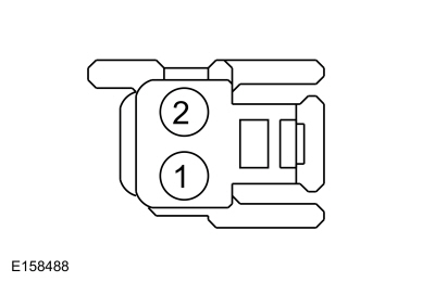 C335-1, component side

 C335-2, component side


 C334-2, component side

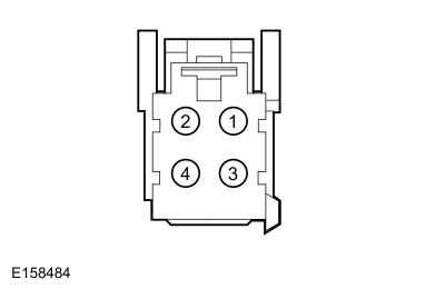 C334-2, component side

 C334-3, component side
 Click here to access the guided routine (FCIM).
 Internet Explorer version 11 or later is required to perform this Pinpoint test.
 WARNING: Turn the ignition OFF and wait one minute to discharge the backup power supply. Failure to follow this instruction may result in serious injury or death in the event of an accidental deployment. Ignition OFF.
 Click here to access the guided procedure (BCM).
 Internet Explorer version 11 or later is required to perform this Pinpoint test.
 Click here to access the guided routine (FCIM).
 Internet Explorer version 11 or later is required to perform this Pinpoint test.
 WARNING: Incorrect repair methods or actions may cause unintentional deployment of the supplemental restraint system (SRS). Never compromise or deviate from these instructions. Failure to follow all instructions exactly may result in serious injury due to unintentional deployment.
 WARNING: Turn the ignition OFF and wait one minute to discharge the backup power supply. Failure to follow this instruction may result in serious injury or death in the event of an accidental deployment. Ignition OFF.


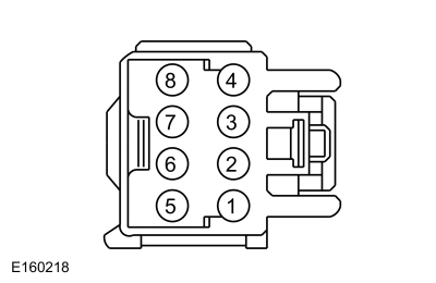 C3035-5, component side

 C3035-8, component side
 WARNING: Turn the ignition OFF and wait one minute to discharge the backup power supply. Failure to follow this instruction may result in serious injury or death in the event of an accidental deployment. Ignition OFF.


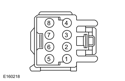 C3035-3, component side

 C3035-4, component side
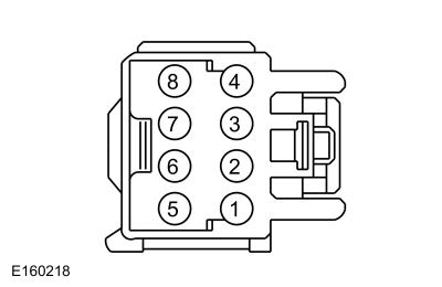 C3035-7, component side

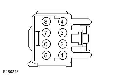 C3035-4, component side
 WARNING: Turn the ignition OFF and wait one minute to discharge the backup power supply. Failure to follow this instruction may result in serious injury or death in the event of an accidental deployment. Ignition OFF.

 C3035-5, component side

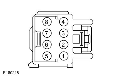 C3035-8, component side

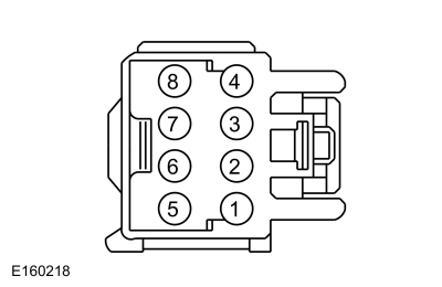 C3035-1, component side

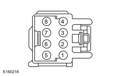 C3035-2, component side
 WARNING: Turn the ignition OFF and wait one minute to discharge the backup power supply. Failure to follow this instruction may result in serious injury or death in the event of an accidental deployment. Ignition OFF.
 WARNING: Incorrect repair methods or actions may cause unintentional deployment of the supplemental restraint system (SRS). Never compromise or deviate from these instructions. Failure to follow all instructions exactly may result in serious injury due to unintentional deployment.
 WARNING: Turn the ignition OFF and wait one minute to discharge the backup power supply. Failure to follow this instruction may result in serious injury or death in the event of an accidental deployment. Ignition OFF.


 C3034-5, component side

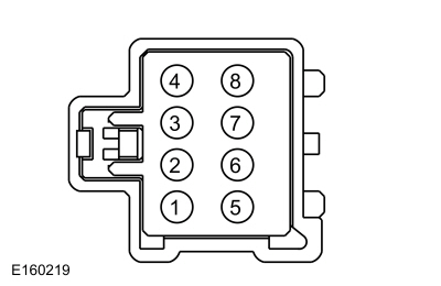 C3034-8, component side
 WARNING: Turn the ignition OFF and wait one minute to discharge the backup power supply. Failure to follow this instruction may result in serious injury or death in the event of an accidental deployment. Ignition OFF.


 C3034-3, component side

 C3034-4, component side
 C3034-7, component side

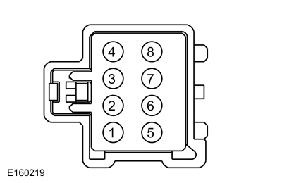 C3034-4, component side
 WARNING: Turn the ignition OFF and wait one minute to discharge the backup power supply. Failure to follow this instruction may result in serious injury or death in the event of an accidental deployment. Ignition OFF.

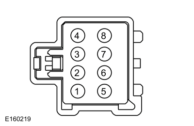 C3034-5, component side

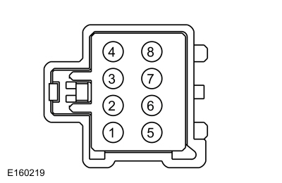 C3034-8, component side

 C3034-1, component side

 C3034-2, component side
 WARNING: Turn the ignition OFF and wait one minute to discharge the backup power supply. Failure to follow this instruction may result in serious injury or death in the event of an accidental deployment. Ignition OFF.
 WARNING: Incorrect repair methods or actions may cause unintentional deployment of the supplemental restraint system (SRS). Never compromise or deviate from these instructions. Failure to follow all instructions exactly may result in serious injury due to unintentional deployment.
 WARNING: Turn the ignition OFF and wait one minute to discharge the backup power supply. Failure to follow this instruction may result in serious injury or death in the event of an accidental deployment. Ignition OFF.


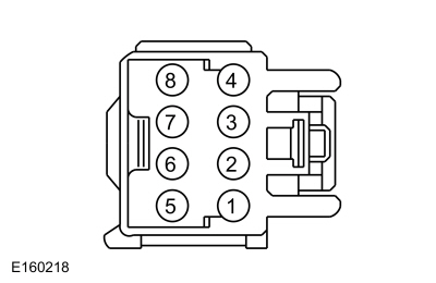 C3040-5, component side

 C3040-8, component side
 WARNING: Turn the ignition OFF and wait one minute to discharge the backup power supply. Failure to follow this instruction may result in serious injury or death in the event of an accidental deployment. Ignition OFF.


 C3040-3, component side

 C3040-4, component side
 C3040-7, component side

 C3040-4, component side
 WARNING: Turn the ignition OFF and wait one minute to discharge the backup power supply. Failure to follow this instruction may result in serious injury or death in the event of an accidental deployment. Ignition OFF.

 C3040-5, component side

 C3040-8, component side

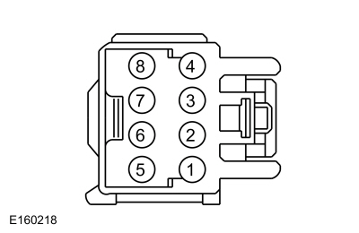 C3040-1, component side

 C3040-2, component side
 WARNING: Turn the ignition OFF and wait one minute to discharge the backup power supply. Failure to follow this instruction may result in serious injury or death in the event of an accidental deployment. Ignition OFF.
 WARNING: Incorrect repair methods or actions may cause unintentional deployment of the supplemental restraint system (SRS). Never compromise or deviate from these instructions. Failure to follow all instructions exactly may result in serious injury due to unintentional deployment.
 WARNING: Turn the ignition OFF and wait one minute to discharge the backup power supply. Failure to follow this instruction may result in serious injury or death in the event of an accidental deployment. Ignition OFF.


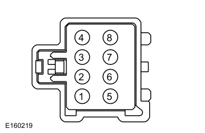 C3039-5, component side

 C3039-8, component side
 WARNING: Turn the ignition OFF and wait one minute to discharge the backup power supply. Failure to follow this instruction may result in serious injury or death in the event of an accidental deployment. Ignition OFF.


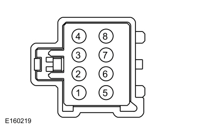 C3039-3, component side

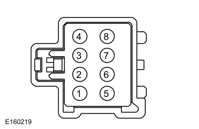 C3039-4, component side
 C3039-7, component side

 C3039-4, component side
 WARNING: Turn the ignition OFF and wait one minute to discharge the backup power supply. Failure to follow this instruction may result in serious injury or death in the event of an accidental deployment. Ignition OFF.

 C3039-5, component side

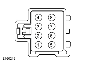 C3039-8, component side

 C3039-1, component side

 C3039-2, component side
 WARNING: Turn the ignition OFF and wait one minute to discharge the backup power supply. Failure to follow this instruction may result in serious injury or death in the event of an accidental deployment. Ignition OFF.
 WARNING: Incorrect repair methods or actions may cause unintentional deployment of the supplemental restraint system (SRS). Never compromise or deviate from these instructions. Failure to follow all instructions exactly may result in serious injury due to unintentional deployment.
 C3035-1, component side

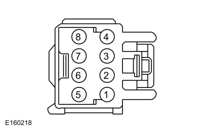 C3035-2, component side
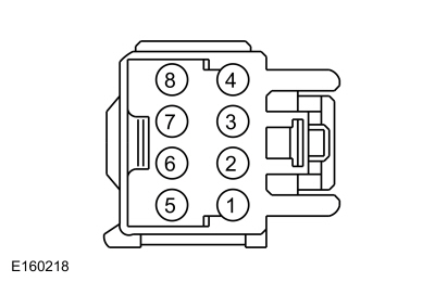 C3035-3, component side

 C3035-4, component side
 C3035-3, component side

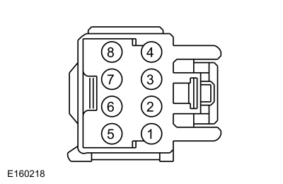 C3035-7, component side
 C3035-5, component side

 C3035-8, component side
 WARNING: Turn the ignition OFF and wait one minute to discharge the backup power supply. Failure to follow this instruction may result in serious injury or death in the event of an accidental deployment. Ignition OFF.


 WARNING: Turn the ignition OFF and wait one minute to discharge the backup power supply. Failure to follow this instruction may result in serious injury or death in the event of an accidental deployment. Ignition OFF.
 WARNING: Incorrect repair methods or actions may cause unintentional deployment of the supplemental restraint system (SRS). Never compromise or deviate from these instructions. Failure to follow all instructions exactly may result in serious injury due to unintentional deployment.
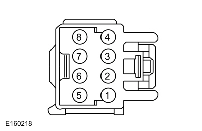 C3040-1, component side

 C3040-2, component side
 C3040-3, component side

 C3040-4, component side
 C3040-3, component side

 C3040-7, component side
 C3040-5, component side

 C3040-8, component side
 WARNING: Turn the ignition OFF and wait one minute to discharge the backup power supply. Failure to follow this instruction may result in serious injury or death in the event of an accidental deployment. Ignition OFF.


 WARNING: Turn the ignition OFF and wait one minute to discharge the backup power supply. Failure to follow this instruction may result in serious injury or death in the event of an accidental deployment. Ignition OFF.
 WARNING: Incorrect repair methods or actions may cause unintentional deployment of the supplemental restraint system (SRS). Never compromise or deviate from these instructions. Failure to follow all instructions exactly may result in serious injury due to unintentional deployment.
 C3034-1, component side

 C3034-2, component side
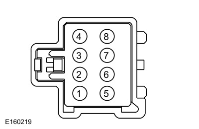 C3034-3, component side

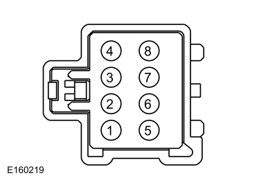 C3034-4, component side
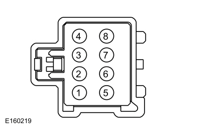 C3034-3, component side

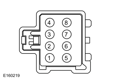 C3034-7, component side
 C3034-5, component side

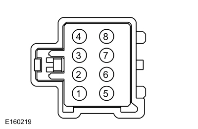 C3034-8, component side
 WARNING: Turn the ignition OFF and wait one minute to discharge the backup power supply. Failure to follow this instruction may result in serious injury or death in the event of an accidental deployment. Ignition OFF.


 WARNING: Turn the ignition OFF and wait one minute to discharge the backup power supply. Failure to follow this instruction may result in serious injury or death in the event of an accidental deployment. Ignition OFF.
 WARNING: Incorrect repair methods or actions may cause unintentional deployment of the supplemental restraint system (SRS). Never compromise or deviate from these instructions. Failure to follow all instructions exactly may result in serious injury due to unintentional deployment.
 C3039-1, component side

 C3039-2, component side
 C3039-3, component side

 C3039-4, component side
 C3039-3, component side

 C3039-7, component side
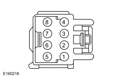 C3039-5, component side

 C3039-8, component side
 WARNING: Turn the ignition OFF and wait one minute to discharge the backup power supply. Failure to follow this instruction may result in serious injury or death in the event of an accidental deployment. Ignition OFF.


 WARNING: Turn the ignition OFF and wait one minute to discharge the backup power supply. Failure to follow this instruction may result in serious injury or death in the event of an accidental deployment. Ignition OFF.
 Click here to access the guided routine (PCM).
 Internet Explorer version 11 or later is required to perform this Pinpoint test.
 Click here to access the guided procedure (BCM).
 Internet Explorer version 11 or later is required to perform this Pinpoint test.
 Click here to access the guided routine (FCIM).
 Internet Explorer version 11 or later is required to perform this Pinpoint test.