Automatic Transmission
Transmission Control Module (TCM) Circuit Diagrams
In this manual: Automatic Transmission
~3min read
TCM Connector and Terminal Function
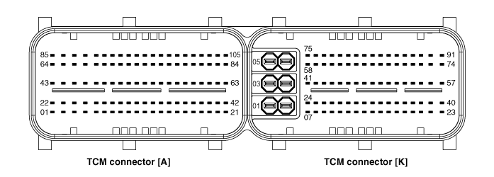
TCM Terminal Function
| Connector [A] | Connector [K] | ||
| Pin | Description | Pin | Description |
| A1 | Overdrive Clutch Control Solenoid Valve (OD/C_VFS) |
K8 | FLEXRAY COMM. Signal HIGH |
| A5 | Torque Converter Control Solenoid (T/CON_VFS) |
K25 | FLEXRAY COMM. Signal LOW |
| A6 | Pressure Control Solenoid (VFS-LINE) | K59 | CAN LOW |
| A7 | 2-6 Brake Control Solenoid Valve (26/B_VFS) | K60 | CAN (LOW) |
| A8 | Inhibitor Switch Signal "S2" | K76 | CAN HIGH |
| A9 | Sport Mode Down Switch | K77 | CAN (HIGH) |
| A10 | Sport Mode Up Switch | ||
| A22 | Underdrive Brake Control Solenoid Valve (UD/B_VFS) |
||
| A26 | 35R Clutch Control Solenoid Valve (35R/C_VFS) |
||
| A27 | Inhibitor Switch Signal "S1" | ||
| A30 | Sport Mode Select Switch | ||
| A43 | Solenoid Power 1 (A1, A5, A26, A48) | ||
| A44 | Solenoid Power 2 (A6, A7, A22, A47) | ||
| A45 | Ground (Power) | ||
| A46 | Ground (Power) | ||
| A47 | On/Off Solenoid Valve (SS-B) | ||
| A48 | On/Off Solenoid Valve A (SS-A) | ||
| A49 | Oil Temperature Sensor (-) | ||
| A64 | VB (Battery Voltage) | ||
| A68 | Shift Lock Solenoid Control | ||
| A70 | Inhibitor Switch Signal "S3" | ||
| A72 | Input Speed Sensor Signal | ||
| A73 | Output Speed Sensor Power | ||
| A85 | VB (Battery Voltage) | ||
| A91 | Transmission Fluid Temperature Sensor (+) | ||
| A92 | Output Speed Sensor Signal | ||
| A93 | "S4" Inhibitor Switch Signal | ||
| A94 | Input Speed Sensor Power | ||
TCM Terminal Input/Output Signal
| Pin | Description | Condition | Input/Output Value | |
| Type | Level | |||
| A1 | Overdrive Clutch Control Solenoid Valve (OD/C_VFS) |
- | Output | 0 V/Battery Voltage Level |
| 9 V < Battery Voltage Level < 16 V | ||||
| A5 | Torque Converter Control Solenoid Valve (T/C_VFS) |
- | Output | 0 V/Battery Voltage Level |
| 9 V < Battery Voltage Level < 16 V | ||||
| A6 | Line Pressure Control Solenoid Valve (LINE_VFS) |
- | Output | 0 V/Battery Voltage Level |
| 9 V < Battery Voltage Level < 16 V | ||||
| A7 | Brake 26 Control Solenoid Valve (26/B_VFS) |
- | Output | 0 V/Battery Voltage Level |
| 9 V < Battery Voltage Level < 16 V | ||||
| A8 | Inhibitor Switch Signal "S2" | High | Input | 0 V/Battery Voltage Level |
| Low | 9 V < Battery Voltage Level < 16 V | |||
| A9 | Sport Mode Down Switch | Down | Input | 0 V/Battery Voltage Level |
| Other | 9 V < Battery Voltage Level < 16 V | |||
| A10 | Sport Mode Up Switch | On | Input | 0 V/Battery Voltage Level |
| Other | 9 V < Battery Voltage Level < 16 V | |||
| A22 | Underdrive Brake Control Solenoid Valve (UD/B_VFS) |
- | Output | 0 V/Battery Voltage Level |
| 9 V < Battery Voltage Level < 16 V | ||||
| A26 | 35R Clutch Control Solenoid Valve (35R/C_VFS) |
- | Output | 0 V/Battery Voltage Level |
| 9 V < Battery Voltage Level < 16 V | ||||
| A27 | Inhibitor Switch Signal "S1" | High | Input | 0 V/Battery Voltage Level |
| Low | 9 V < Battery Voltage Level < 16 V | |||
| A30 | Sport Mode Select Switch | Sport Mode | Input | 0 V/Battery Voltage Level |
| Other | 9 V < Battery Voltage Level < 16 V | |||
| A43 | Solenoid 1 Power (A1, A5, A26, A48) |
Power | 0 V/Battery Voltage Level | |
| 9 V < Battery Voltage Level < 16 V | ||||
| A44 | Solenoid 2 Power (A6, A7, A22, A47) |
Power | 0 V/Battery Voltage Level | |
| 9 V < Battery Voltage Level < 16 V | ||||
| A47 | On/Off Solenoid Valve (SS-B) | High | Output | 0 V/Battery Voltage Level |
| Low | 9 V < Battery Voltage Level < 16 V | |||
| A48 | On/Off Solenoid Valve A (SS-A) | High | Output | 0 V/Battery Voltage Level |
| Low | 9 V < Battery Voltage Level < 16 V | |||
| A49 | Oil Temperature Sensor (-) | - | Ground | 0 V |
| A70 | Inhibitor Switch Signal "S3" | High | Input | 0 V/Battery Voltage Level |
| Low | 9 V < Battery Voltage Level < 16 V | |||
| A72 | Input Speed Sensor Signal | High | Input | 0.7 V/1.4 V |
| Low | ||||
| A73 | Output Speed Sensor Power | ON | Power | 0 V/7.5 V |
| OFF | ||||
| A91 | Transmission Fluid Temperature Sensor (+) | ON | Input | 0 V/3.3 V |
| OFF | ||||
| A92 | Output Speed Sensor Signal | High | Input | 0.7 V/1.4 V |
| Low | ||||
| A93 | "S4" Inhibitor Switch Signal | High | Input | 0 V/Battery Voltage Level |
| Low | 9 V < Battery Voltage Level < 16 V | |||
| A94 | Input Speed Sensor Power | ON | Power | 0 V/7.5 V |
| OFF | ||||
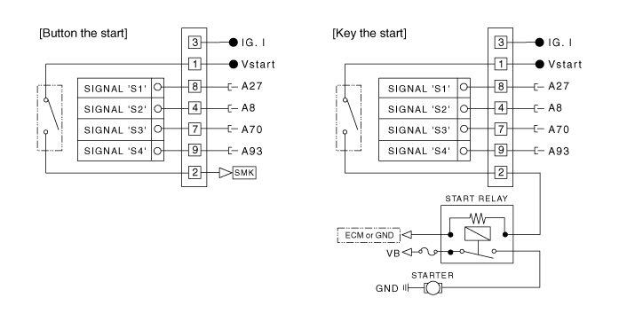
Wiring Diagram

Test yourself
A quick Hyundai Elantra AD quiz: every answer comes with an explanation and a link to the manual page.
Was this page helpful?