Suspension System
Description and Operation
In this manual: Suspension System
11steps
~66min
3/5difficulty
Done 0 of 11
Description
Continuous real-time control of damping force according to vehicle operating conditions and road surface conditions improves ride comfort and steering stability, including reduction of body roll/pitch in case of vehicle dynamics control, quick cornering, braking and starting. Continuously Controlled Damper: The current of the variable damping force solenoid valve is controlled by the ECU. Depending on the change in current amount, the spool valve moves in the actuator to change the flow direction and change the damping force. Front Continuously Controlled Damper


| Item | Waveform | Function |
| Body G-Sensor | 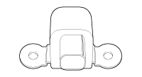 |
Body Motion Detection Skyhook Damping Control (Pitch, Bounce) |
| Wheel G-Sensor | 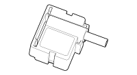 |
Wheel Roughness Detection Damper Speed Estimation |
| Vehicle Signals | Vehicle Speed Throttle Position Sensor Brake Steering Angle Drive Mode Select Signal |
|
| Steering Wheel Angle Sensor |  |
Driver Steering Input Estimation Lateral Acceleration Measurements |
ECU: The current of the variable damping force solenoid valve is controlled by the ECU.

Operation
System: Checks the MCU and the condition of each part when power is supplied to the ECU and prepares for operation. The ECU controls the actuator when the engine is running.Operating Modes: Normal Operation: 4 types of driver-selected modes, such as NORMAL or ECO, or SNOW and SPORT. The mode is changed by linking with the Drive Mode Integrated Control.
Fail-Safe Mode: When a malfunction is detected, the system switches to the corresponding fail-safe mode depending on the fault type and the warning light flashes.
Damping Control: Damping control improves both ride comfort and steering stability. It is performed through Skyhook control and adaptive control. Skyhook classifies body motion into bounce, roll and pitch and controls each separately. Special driving conditions, such as quick lane change, rapid acceleration and sudden starting, limit the maximum solenoid current to ensure vehicle stability. The solenoid of each wheel is controlled by PWM, and the target current is output through electric current control.
Skyhook: Vertical movement of the vehicle body is controlled by monitoring the vertical acceleration of the body and wheels. Skyhook controls the solenoid current for each wheel in proportion to the calculated valve speed.
- Road Surface Determination. The damping control determines the road surface condition using the vertical acceleration sensors on the front wheel, body, and wheels. The road surface is classified into 5 types: smooth road, rough road 1, rough road 2, bumpy road, and jerky road. The road surface is determined by checking the acceleration signal intensity and frequency. The damping force is determined according to the road surface determination and the preset priority, and the calibration parameter is used to calculate the target electric current. The road surface determination parameter can be adjusted by calibration.
- Skyhook Control. The body bounce velocity can be obtained by adding the vertical velocities of the four wheels. The vertical velocity of the vehicle body can be estimated by integrating the acceleration signal. The required damping force is calculated by multiplying the proportional gain by the bounce velocity and passing the result through a maximum value limit function. Calibration parameters are the gain and the limit value. The front and rear wheels have different values.
- Pitch Control. The body pitch velocity can be obtained from the difference in body velocity between the front and rear wheels. The required damping force is calculated by multiplying the proportional gain by the pitch velocity and passing the result through a maximum value limit function. Calibration parameters are the gain and the limit value. The front and rear wheels have different values.
- Roll Control. The body roll velocity can be obtained from the difference in body velocity between the left and right sides of the vehicle. The required damping force is calculated by multiplying the proportional gain by the roll velocity and passing the result through a maximum value limit function. Calibration parameters are the gain and the limit value. The front and rear wheels have different values.
- Damper Velocity Estimation. The damper velocity can be estimated from the difference between the vertical velocities of the body and the wheel. The vertical velocities of the body and wheel are obtained by integrating the acceleration sensor signal. The rear wheel acceleration can be estimated from the front wheel acceleration using the time delay and vehicle speed.
- Directional Check. The final damping force required for Skyhook control is determined by the "passive state" condition. The passive check determines Y/N for damping force control. The final required damping force is set using the control solenoid electric current when the required damping force and the damper velocity are in the same direction. If they are in opposite directions, it is set as the soft damping force.
- Anti-Roll Control. The lateral movement of the vehicle can be estimated from the steering angle sensor and the vehicle speed. The maximum electric current control is limited when the lateral jerk signal exceeds the set value. The calibration parameters are the jerk signal level control, the damping force, and the damping force control amount. They can be set according to vehicle speed.
- Anti-Dive Control. The vehicle deceleration during braking is calculated from the difference in vehicle speeds. The maximum electric current control is limited when the calculated deceleration is greater than the set value. The calibration parameters are the deceleration level and the damping force control amount.
- Anti-Squat Control. The driver's intention to accelerate can be anticipated from the accelerator pedal position information at the start. The maximum electric current control is limited during acceleration when the position is outside the set value. The calibration parameters are the deceleration level and the damping force control amount.
- Vehicle Speed Control. This function maintains a minimum damping force depending on the vehicle speed. The maximum electric current is limited. The calibration parameter is the value that controls the damping force depending on the vehicle speed.
- Damping Control Mode. The driver can select either of two modes (Auto and Sport). Damping mode switching is linked to the Drive Mode Integrated Control system. ECS control is performed in AUTO mode when NORMAL, ECO, or SNOW mode is selected with the drive mode integrated switch. ECS control is performed in SPORT mode when SPORT mode is selected. The calibration parameters stored in the ECU change depending on the selected damping control mode, and the vehicle handling may differ for each mode. Ride comfort and steering stability are optimized in AUTO mode overall. SPORT mode focuses on steering stability.
Test yourself
A quick Hyundai Genesis DH quiz: every answer comes with an explanation and a link to the manual page.
Was this page helpful?