Suspension System

Front Lower Arm Repair Procedures

32steps
~197min
5/5difficulty
1special tools
04080120160200107.980N·mlb·ft
Tightening torque found on this page
Done 0 of 32

Replacement

[4WD]

Remove the side arm.
  1. Loosen the wheel nuts slightly. Raise the vehicle and make sure it is securely supported.
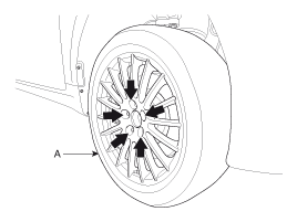
  2. Remove the front wheel and tire (A) from the front hub.

    Tightening torque: 88.3 ~ 108 N·m

    Be careful not to damage the hub bolts when removing the front wheel and tire.
  3. Loosen the steering gear mounting bolts and pull the steering gear downward.

    Tightening torque: 88.3 ~ 108 N·m

  4. Loosen the flange bolt and lock nut.

    Tightening torque: 137.3 - 157 N·m N·m (14.0 - 16.0 kgf·m, 101.3 - 115.7 ft-lbf)

    [RH]
    [LH]
  5. Remove the shoulder bolt and lock nut (A) to disconnect the side arm from the strut assembly (B).

    Tightening torque: 137.3 ~ 157 N·m (14.0 ~ 16.0 kgf·m, 101.3 ~ 115.7 lbf·ft)

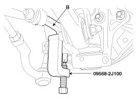
  6. Remove the cotter pin and nut. Then disconnect the side arm from the steering knuckle using SST (09568-2J100).

    Tightening torque: 88.3 ~ 108 N·m

  7. Install in the reverse order of removal.
  8. Check the front alignment. (Refer to Wheels/Tires - "Camber and Toe")
  9. Loosen the wheel nuts slightly. Raise the vehicle and make sure it is securely supported.
  10. Remove the front wheel and tire (A) from the front hub.

    Tightening torque: 88.3 ~ 108 N·m

    Be careful not to damage the hub bolts when removing the front wheel and tire.
  11. Loosen the nut and remove the compression arm from the steering knuckle.

    Tightening torque: 88.3 ~ 108 N·m

  12. Loosen the shoulder bolt and lock nut, then remove the compression arm (A).

    Tightening torque: 137.3 ~ 157 N·m (14.0 ~ 16.0 kgf·m, 101.3 ~ 115.7 lbf·ft)

  13. Install in the reverse order of removal.
  14. Check alignment. (Refer to Tires/Wheels – Wheel Alignment)
Remove the compression arm.

[2WD]

Remove the side arm.
  1. Loosen the wheel nuts slightly. Raise the vehicle and make sure it is securely supported.
  2. Remove the front wheel and tire (A) from the front hub.

    Tightening torque: 88.3 ~ 108 N·m

    Be careful not to damage the hub bolts when removing the front wheel and tire.
  3. Loosen the steering gear mounting bolts and pull the steering gear downward.

    Tightening torque: 88.3 ~ 108 N·m

  4. Loosen the flange bolt and lock nut.

    Tightening torque: 137.3 - 157 N·m N·m (14.0 - 16.0 kgf·m, 101.3 - 115.7 ft-lbf)

    [RH]
    [LH]
  5. Remove the shoulder bolt and lock nut to disconnect the side arm from the strut assembly.

    Tightening torque: 137.3 ~ 157 N·m (14.0 ~ 16.0 kgf·m, 101.3 ~ 115.7 lbf·ft)

    • Before tightening the bolts, make sure the orientation is correct.
    • Tightening the bolts in the opposite direction results in insufficient clearance between the links.
  6. Loosen the cotter pin and nut, then remove the side arm using SST (09568-2J100).

    Tightening torque: 88.3 ~ 108 N·m

  7. Install in the reverse order of removal.
  8. Check the front alignment. (Refer to Wheels/Tires - "Camber and Toe")
  9. Loosen the wheel nuts slightly. Raise the vehicle and make sure it is securely supported.
  10. Remove the front wheel and tire (A) from the front hub.

    Tightening torque: 88.3 ~ 108 N·m

    Be careful not to damage the hub bolts when removing the front wheel and tire.
  11. Remove the cotter pin and castellated nut from the end of the tie rod (A) and the tension arm (B). Tightening torque: Tie rod: 88.3 ~ 108 N·m Tension arm: 88.3 ~ 108 N·m
  12. Apply grease to the special service tool (09568-2J100) as shown in the following illustration. Then use the special service tool to separate the tie rod end (A) and tension arm (B) from the steering knuckle.
  13. Remove the flange bolt and lock nut to remove the tension arm (A) from the frame.

    Tightening torque: 137.3 ~ 157 N·m (14.0 ~ 16.0 kgf·m, 101.3 ~ 115.7 lbf·ft)

    Tightening the bolts in the reverse direction makes it more difficult to install the subframe, so pay attention to the installation direction during assembly.
  14. Install in the reverse order of removal.
  15. Check alignment. (Refer to Tires/Wheels – Wheel Alignment)
Remove the tension arm.

Inspection

  1. Inspect the lower arm bushings for damage or signs of aging. If necessary, replace the lower arm assembly.
  2. Inspect the side arm for damage or deformation.
  3. Inspect all bolts.

Test yourself

A quick Hyundai Genesis DH quiz: every answer comes with an explanation and a link to the manual page.