Drive Shaft and Axle
FRONT DRIVE SHAFT Repair Procedures
In this manual: Drive Shaft and Axle
31steps
~191min
5/5difficulty
1special tools
Done 0 of 31
DEPOSIT
- Loosen the wheel nuts slightly. Raise the vehicle and make sure it is securely supported.
- Remove the front wheel and tire assembly from the hub.
Tightening torque: 107.9 - 128 N·m
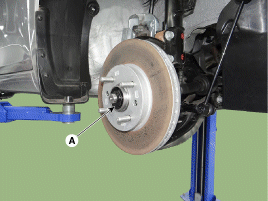
- Loosen the hub nut (A).
Tightening torque: 274.6 ~ 294 N·m (28.0 ~ 30.0 kgf·m, 202.5 ~ 217.1 lbf·ft)
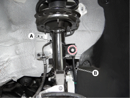
- Remove the stabilizer bar link (B) from the crossmember assembly by loosening the nut (A).
Tightening torque: 98.1 ~ 118 N·m
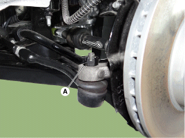
- Remove the cotter pin and loosen the castellated nut (A).
Tightening torque: 23.5 ~ 33 N·m
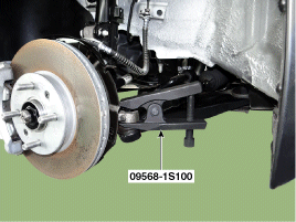
- Separate the ball joint from the tie rod end using SST (09568-1C100).
- Loosen the nut (A) and separate the ball joint from the lower arm.
Tightening torque: 58.8 ~ 71 N·m
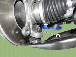
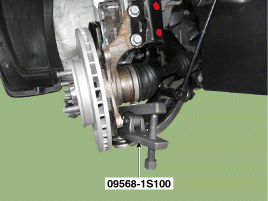
- Disconnect the drive shaft (A) from the front hub assembly.

- Insert a lever (A) between the transaxle case and the seal housing (B), and separate the drive shaft from the transaxle.
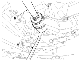
- To install, perform the removal procedure in reverse order.
Inspection
- Check that the drive shaft boots are not damaged or deteriorated.
- Check the drive shaft splines for wear or damage.
DISASSEMBLY
- Remove the snap ring (B) from the spline of the drive shaft (A).
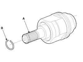
- Remove the two bellows seal clamps from the transaxle side seal housing. (TJ)
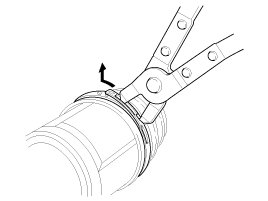
- Remove the bellows seal from the gear side seal (B).
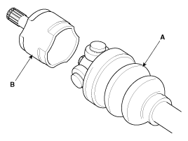
- When separating the bellows from the bellows joint (A) on the transmission side, remove the grease from the housing (B) and separate the two parts.
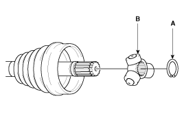
- Remove the snap ring (A) and roller cross (B) from the shaft.
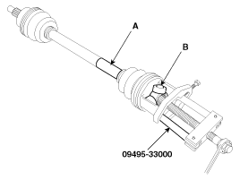
- Disconnect the cross assembly (B) from the drive shaft (A) using the special service tool (09495-33000).
- Clean the entire cross assembly.
- Remove the bellows (A) from the bellows joint (TJ) on the transaxle side.
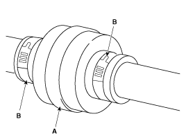
- Using pliers or a flat-tip screwdriver (-), remove the dynamic damper clamps (B) (A).
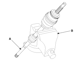
- Secure the drive shaft (A) in a vise (B) as shown in the illustration.
- Apply powder soap to the shaft to prevent damage to the part between the shaft spline and the dynamic damper when removing the dynamic damper.
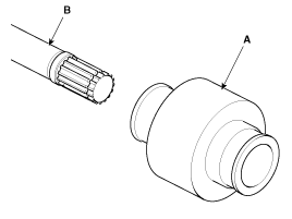
- Carefully separate the dynamic damper (A) from the shaft (B).
Installation
- Wrap insulation tape around all splines of the drive shaft (TJ) to avoid damaging the dust covers.
- Apply grease to the wheel-side bellows seals, then install the bellows.
- Install the caliper.
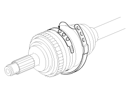
- Install the boots and bellows seal on the transaxle side.
- Using the alignment marks (D) made during disassembly to facilitate installation, install the cross assembly (A) and elastic ring (B) onto the splines of the transmission shaft (C).
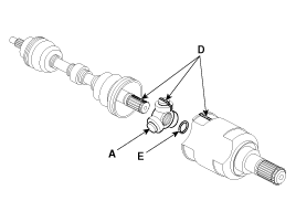
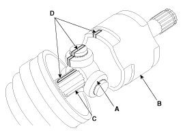
- Add the specified grease to the bellows in the amount removed for inspection.
- Install two sealing bands.
Test yourself
A quick Hyundai i20 quiz: every answer comes with an explanation and a link to the manual page.
Was this page helpful?