Exhaust Butterfly Valve Actuator Installation
- Install the pulley [A] on the actuator so that the hole side [B] align with the groove [C] on the shaft.
Make sure that the groove on the shaft is pointing toward the center of the screw [D].
If the shaft position is incorrect, refer to the following NOTE and procedures to electrically adjust the shaft position.
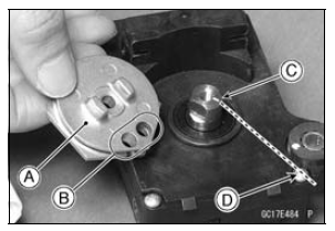
- Install the pulley [A] on the actuator as shown.
- Tighten the pulley bolt [B] while holding the pulley with the suitable tool [C].
Torque - Exhaust Butterfly Valve Actuator Pulley Bolt: 4.9 NВ·m (0.50 kgfВ·m, 43 inВ·lb)
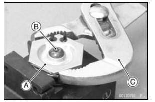
NOTICE
If the pulley bolt is tightened without holding, the actuator damage will occur.
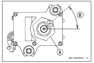
- After tightening the pulley bolt, confirm whether pulley [A] is an angle shown in the figure.
This position is original position of the pulley.
NOTE
Correct the position electrically after confirming the use is discontinued and there is no damage when differing from the angle of shown in the figure.
NOTICE
Do not correct the pulley position with the tool, forcibly. The actuator damage will occur.
If the pulley angle is wrong, adjust the angle as follows.
Connect: 2 pins Connector 3 pins Connector
Turn the ignition switch to ON.
Confirm the pulley turns clockwise or counterclockwise then it stops at the original position.
If the pulley position has not been returned to the original position, electrically adjust the shaft position as follows.
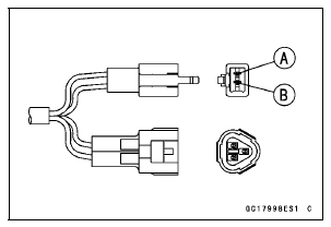
Remove: 2 pins Connector 3 pins Connector
Turn the pulley to the original position by turning it clockwise or counterclockwise by connecting the battery to the 2 pin connector terminals. To turn the pulley gradually, intermittently connect the battery positive (+) terminal to the 2 pin connector terminal while connecting the battery negative (–) terminal to the connector.
Pink (–) lead terminal [A] Gray (+) lead terminal [B]
Clockwise: Pink (–) lead terminal to battery (–) terminal Gray (+) lead terminal to battery (+) terminal
Counterclockwise: Pink (–) lead terminal to battery (+) terminal Gray (+) lead terminal to battery (–) terminal
Reconnect the 2 pins connector and 3 pins connector, and turn the ignition switch ON.
Make sure that the pulley turns clockwise and then counterclockwise.
The pulley should returns to the original position.
Turn the ignition switch OFF.
If the pulley does not return to the original position, check the exhaust butterfly valve actuator resistance (see Exhaust Butterfly Valve Actuator Resistance Inspection).
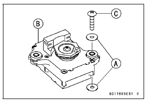
- Be sure to install the washers [A] on the exhaust butterfly valve actuator [B].
- Tighten: Torque - Exhaust Butterfly Valve Actuator Mounting Screws [C]: 1.2 N В·m (0.12 kgf В·m, 11 inВ·lb)
- Install the close cable first and then open cable (see Exhaust Butterfly Valve Cable Installation in the Engine Top End chapter).
Test yourself
A quick Kawasaki Ninja ZX-10R quiz: every answer comes with an explanation and a link to the manual page.