Oxygen Sensor - not activated (Service Code 33, Equipped Models)
Oxygen Sensor Removal/Installation
Refer to the Oxygen Sensor Removal/Installation (Equipped Models) in the Electrical System chapter.
Oxygen Sensor Inspection
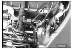
- Remove: Fuel Tank (see Fuel Tank Removal in the Fuel System (DFI) chapter) Oxygen Sensor Lead Connector [A]
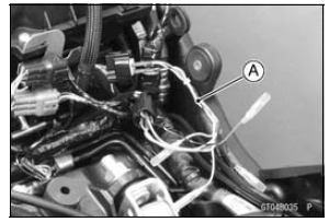
- Connect the measuring adapter [A] between the harness connector and oxygen sensor lead connector.
Special Tool - Measuring Adapter: 57001-1700
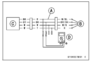
- Connect a digital meter [D] to the measuring adapter leads.
Oxygen Sensor Output Voltage Connections to Adapter: Digital Meter (+) → R (sensor BK) lead Digital Meter (–) → BK (sensor GY) lead
- Remove the air switching valve [A] (see Air Switching Valve Removal in the Engine Top End chapter).
Do not disconnect the air switching valve connector [B].
- Remove the hoses [C].
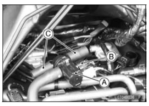
- Install the suitable plugs [A] on the fitting of the air suction valve covers, and shut off the secondary air.
- Install the following parts temporarily.
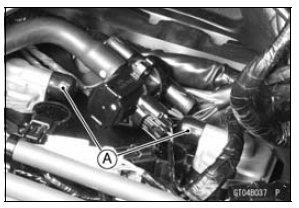
- Warm up the engine thoroughly until the radiator fan starts.
- Measure the output voltage with the connector joined.
Output Voltage (with Plugs, Rich) Standard: DC 0.8 V or more
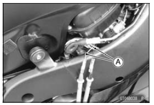
- Turn the ignition switch to OFF.
- Remove the air cleaner housing (see Air Cleaner Housing Removal in the Fuel System (DFI) chapter).
- Remove the plugs from the fittings [A].
The engine gets extremely hot during normal operation and can cause serious burns. Never touch a hot engine.
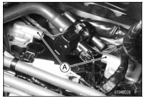
- Install the following parts temporarily.
Air Cleaner Housing (see Air Cleaner Housing Installation in the Fuel System (DFI) chapter) Fuel Tank (see Fuel Tank Installation in the Fuel System (DFI) chapter)
- Start the engine, and let it idle.
- Measure the output voltage with the connector joined.
Output Voltage (without Plugs, Lean) Standard: DC 0.24 V or less
- Turn the ignition switch to OFF.
If the reading is out of the standard (with plugs: 0.8 V or more, without plugs: 0.24 V or less), remove the ECU and check the wiring for continuity between harness connectors.
Special Tool - Hand Tester: 57001-1394
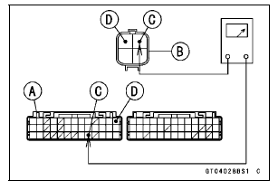
Disconnect the ECU and sensor connectors.
Wiring Continuity Inspection ECU Connector [A] ←→ Oxygen Sensor Connector [B] W/BL lead (ECU terminal 35) [C] BR/BK lead (ECU terminal 13) [D]
If the wiring is good, replace the sensor.
If the reading is within the standard (with plugs: 0.8 V or more, without plugs: 0.24 V or less), check the ECU for its ground and power supply (see ECU Power Supply Inspection in the Fuel System (DFI) chapter).
If the ground and power supply are good, replace the ECU (see ECU Removal/Installation in the Fuel System (DFI) chapter).
Oxygen Sensor Circuit
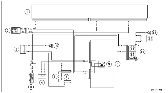
1. ECU
2. Oxygen Sensor
3. Ignition Switch
4. Joint Connector F
5. Joint Connector A
6. Fuse Box 1
7. Ignition Fuse 15 A
8. Relay Box
9. ECU Main Relay
10. Frame Ground 3
11. Starter Relay
12. ECU Fuse 15 A
13. Main Fuse 30 A
14. Battery
15. Engine Ground
Test yourself
A quick Kawasaki Ninja ZX-10R quiz: every answer comes with an explanation and a link to the manual page.