Front Wheel Rotation Sensor Signal (Service Code 27)
Front Wheel Rotation Sensor Signal Inspection
The front wheel rotation sensor sends the signal to the ECU through the KIBS hydraulic unit (KIBS equipped models). For other than KIBS equipped models, the signal is sent directly to the ECU.
The ECU uses the wheel rotation sensor signal for KTRC control.
The service code 27 is detected with the ECU.
- When the service code 27 and following service codes (for KIBS) are displayed at the same time, inspect the front wheel rotation sensor.
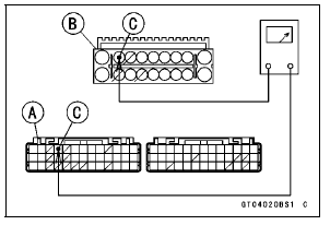
Special Tool - Hand Tester: 57001-1394 Wiring Continuity Inspection ECU Connector [A] ← → KIBS ABS Hydraulic Unit Connector [B] G/Y lead (ECU terminal 4, KIBS Hydraulic Unit terminal 8) [C]
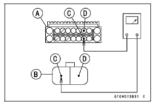
Wiring Continuity Inspection KIBS Hydraulic Unit Connector [A] ← → Front Wheel Rotation Sensor Connector [B] W lead (KIBS Hydraulic Unit Connector terminal 12) [C] Y lead (KIBS Hydraulic Unit Connector terminal 3) [D]
- For other than KIBS equipped models, check the wiring for continuity between harness connectors.
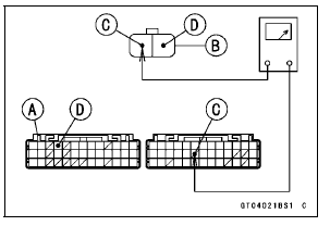
Special Tool - Hand Tester: 57001-1394 Wiring Continuity Inspection ECU Connector [A] ← → Front Wheel Rotation Sensor Connector [B] R lead (ECU terminal 58) [C] G/Y lead (ECU terminal 4) [D]
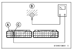
Front Resistor Resistance (in Main Harness) Connections: ECU Connector [A] ← → Ground [B] G/Y lead (ECU terminal 4) [C] Standard: 209  231 Ω
If the resistance is out of the standard, replace the main harness.
If the wiring is good, check the ECU for its ground and power supply (see ECU Power Supply Inspection in the Fuel System (DFI) chapter).
If the ground and power supply are good, replace the ECU (see ECU Removal/Installation in the Fuel System (DFI) chapter).
Wheel Rotation Sensor Circuit (KIBS Equipped Models)
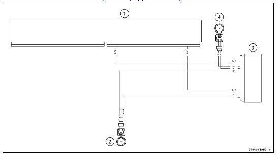
1. ECU
2. Front Wheel Rotation Sensor
3. KIBS Hydraulic Unit
4. Rear Wheel Rotation Sensor
Wheel Rotation Sensor Circuit (other than KIBS Equipped Models)
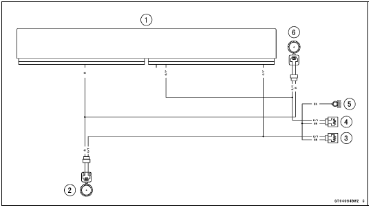
1. ECU
2. Front Wheel Rotation Sensor
3. Resistor F 220 Ω
4. Resistor R 220 Ω
5. Frame Ground 3
6. Rear Wheel Rotation Sensor
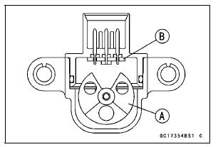
This sensor has a weight [A] with two magnets inside, and sends a signal to the ECU. But when the motorcycle banks 60  70В° or more to either
side (in fact falls down), the weight turns and the signal changes. The ECU senses this change, and stops the fuel pump relay, the fuel injectors and the ignition system.
Hall IC [B] When the motorcycle is down, the ignition switch is left ON. If the starter button is pushed, the electric starter turns but the engine does not start. To start the engine again, raise the motorcycle, turn the ignition switch to OFF, and then turn it to ON.
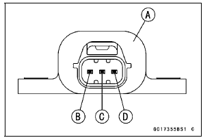
Vehicle-down Sensor [A] Ground Terminal [B]: BR/BK Output Terminal [C]: Y/G Input Terminal [D]: BL
Test yourself
A quick Kawasaki Ninja ZX-10R quiz: every answer comes with an explanation and a link to the manual page.