Gear Position Switch Output Voltage Inspection
NOTE
Be sure the battery is fully charged.

- Turn the ignition switch to OFF.
- Remove the fuel tank (see Fuel Tank Removal in the Fuel System (DFI) chapter).
- Disconnect the sidestand switch/gear position switch lead connector [A].
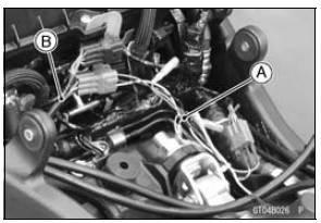
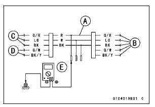
- Connect the measuring adapter [A] between themain harness connector and sidestand switch/gear position switch lead connector as shown in the figure.
Special Tool - Measuring Adapter: 57001-1700
- Connect a digital meter [E] to the measuring adapter lead.
Gear Position Switch Output Voltage Connections to Adapter: Digital Meter (+) → R (sensor G/R) lead Digital Meter (–) → Frame Ground terminal
- Measure the switch input voltage with the engine stopped and with the connector joined.
- Turn the ignition switch to ON.
When changing the gear position from lower gear to higher gear, raise the rear wheel off the ground with a suitable stand and rotate the rear wheel by hand.
Output Voltage at 1  6 Gear
Positions Standard:
1st About DC 3.0 V
2nd About DC 2.5 V
3rd About DC 2.0 V
4th About DC 1.5 V
5th About DC 1.1 V
6th About DC 0.7 V
Turn the ignition switch to OFF
If the reading is out of the standard, check the wiring for continuity, using the wiring diagram in this section.
Special Tool - Hand Tester: 57001-1394
If the wiring is good, check the ECU for its ground and power supply (see ECU Power Supply Inspection in the Fuel System (DFI) chapter).
If the ground and power supply are good, replace the ECU (see ECU Removal/Installation in the Fuel System (DFI) chapter).
Gear Position Switch Circuit
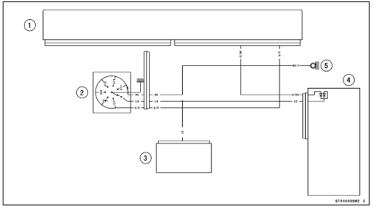
1. ECU
2. Gear Position Switch
3. Meter Unit
4. Relay Box
5. Frame Ground 1
Test yourself
A quick Kawasaki Ninja ZX-10R quiz: every answer comes with an explanation and a link to the manual page.