Engine Mechanical System
Cylinder Block Repair Procedures
In this manual: Engine Mechanical System
50steps
~300min
4/5difficulty
Done 0 of 50
Disassembly
|
|
- Remove the engine assembly from the vehicle. (Refer to Engine and Transaxle Assembly - "Engine and Transaxle Assembly")
- Remove the transaxle assembly from the engine assembly. (Refer to Automatic Transaxle System - "Automatic Transaxle")
- Remove the drive plate and adapter plate. (Refer to Cylinder Block - "Drive Plate")
- Remove the rear oil seal retainer. (Refer to Cylinder Block - "Rear Oil Seal")
- Install the engine on an engine stand for disassembly.
- Remove the exhaust manifold. (Refer to Intake and Exhaust System - "Exhaust Manifold")
- Remove the intake manifold. (Refer to Intake and Exhaust Systems — Intake Manifold)
- Remove the timing chain. (Refer to Valve Timing System - Timing Chain)
- Remove the water temperature control unit. (Refer to Cooling System - "Water Temperature Control Assembly")
- Remove the cylinder head. (Refer to Cylinder Head Assembly - "Cylinder Head")
- Remove the oil pump. (Refer to Lubrication System - "Oil Pump")
- Remove the oil filter housing. (Refer to Lubrication System - "Oil Filter Housing").
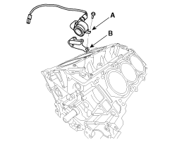
- Remove the oil cap (A) and gasket (B).
- Remove the water jacket spacer. (Refer to Cylinder Block - "Water Jacket Spacer")
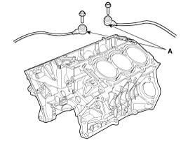
- Remove the knock sensor (A).
- Remove the upper oil pan. (Refer to Lubrication System - "Oil Pan")
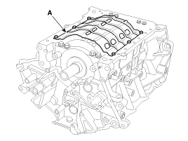
- Remove the baffle (A).
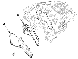
- Remove the oil drain plug (A) and gasket (B).
- Check the connecting rod side clearance. (Refer to Cylinder Block - Piston and Connecting Rod)
- Check the connecting rod cap oil clearance. (Refer to Cylinder Block – Piston and Connecting Rod)
- Remove the piston and connecting rod assembly. (Refer to Cylinder Block - Piston and Connecting Rod)
- Remove the crankshaft main bearing cap and check the oil clearance. (Refer to Cylinder Block - Crankshaft)
- Check the crankshaft end play. (Refer to Cylinder Block - Crankshaft)
- Remove the crankshaft. (Refer to Cylinder Block - Crankshaft)
- Remove the oil jets (A).
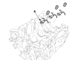
Inspection
Cylinder block- Remove the gasket material. Using a gasket scraper, remove all gasket material from the upper surface of the cylinder block.
- Clean the cylinder block. Using a soft brush and solvent, thoroughly clean the cylinder block.
- Inspect the upper surface of the cylinder block for flatness. Using a precision straightedge and feeler gauge, measure the surface contacting the cylinder head gasket for distortion. Cylinder block gasket surface flatness Standard: less than 0.05 mm (0.0020 in), Limit: less than 0.02 mm (0.0008 in) / 150 x 150
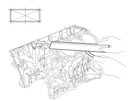
- Inspect Cylinder Bore. Visually inspect the cylinder for vertical scratches. If deep scratches are found, replace the cylinder block.
- Inspect Cylinder Bore. Using a cylinder bore gauge, measure the cylinder bore diameter at the specified positions in the axial and transverse directions.
Standard diameter: 92.00 ~ 92.03 mm (3.6220 ~ 3.6232 in.)
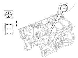
- Check the cylinder bore size code on the cylinder block.
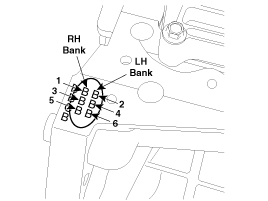
Grade Size code Cylinder Inner Diameter A A 92.00 ~ 92.01 mm
(3.6220 ~ 3.6224 in.)B B 92.01 ~ 92.02 mm
(3.6224 ~ 3.6228 in.)C C 92.02 ~ 92.03 mm
(3.6228 ~ 3.6232 in.) - Select oversize pistons according to the largest cylinder bore diameter.
Identification Mark Size 0,1 0.1 mm (0.004 in) 0,25 0.25 mm (0.010 in)
The piston size is stamped on the top of the piston.
- Measure the outside diameter of the piston to be used.
- Calculate the new bore size based on the measured outside diameter. New bore size = piston outside diameter + 0.03 to 0.05 mm (0.0012 to 0.0020 in) (piston-to-cylinder clearance) - 0.01 mm (0.0004 in) (honing allowance).
- Bore each of the cylinders to the calculated size.
To prevent distortion caused by temperature rise during honing, bore the cylinders in firing order. - Hone the cylinders to the specified size (piston outer diameter + piston-to-cylinder clearance).
- Check the clearance between the piston and cylinder.
Standard: 0.03 to 0.05 mm (0.0012 to 0.0020 in)
When boring cylinders, machine all cylinders to the same oversize. Do not bore only one cylinder to a larger size.
Installation
- Install the oil jets (A).
Tightening torque: 27.5 ~ 31 N·m
- Install the crankshaft. (Refer to Cylinder Block - Crankshaft)
- Install the crankshaft main bearing cap and check the oil clearance. (Refer to Cylinder Block - Crankshaft)
- Check the crankshaft end play. (Refer to Cylinder Block - Crankshaft)
- Install the piston and connecting rod assembly. (Refer to Cylinder Block - Piston and Connecting Rod)
- Check the connecting rod end play. (Refer to Cylinder Block - Piston and Connecting Rod)
- Install the oil drain plug (A) with a new gasket (B).
Tightening torque: 9.8 ~ 11.8 N·m
- Install the baffle plate. Install and evenly tighten the baffle plate bolts in several passes in the specified sequence.
Tightening torque: 9.8 ~ 11.8 N·m

- Install the upper oil pan. (Refer to Lubrication System - Oil Pan)
- Install the knock sensor (A).
Tightening torque: 15.7 ~ 24 N·m
- Install the water jacket separator. (Refer to Cylinder Block - Water Jacket Separator)
- Remove the oil cap (A) and gasket (B).
Tightening torque: 9.8 ~ 11.8 N·m
- Assemble the remaining components in the reverse order of removal.
If replacing the cylinder block with a new one, select the correct crankshaft main bearing and piston according to the crankshaft journal bore mark and the cylinder bore mark stamped on the cylinder block.
- Selection of Crankshaft Main Bearing (Refer to Cylinder Block - Crankshaft)
- Selection of Piston (Refer to Cylinder Block - Piston and Connecting Rod)
Test yourself
A quick Kia Cadenza VG Owner's Manual quiz: every answer comes with an explanation and a link to the manual page.
Was this page helpful?