Body Electrical System
Antenna Repair Procedures
In this manual: Body Electrical System
27steps
~162min
4/5difficulty
Done 0 of 27
Inspection
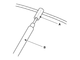
Glass Antenna Test- Wrap aluminum foil (A) around the tip of the tester probe (B), as shown in the illustration.
- Touch one tester probe to the glass antenna terminal (A) and move the other tester probe along the antenna wires to check for continuity.
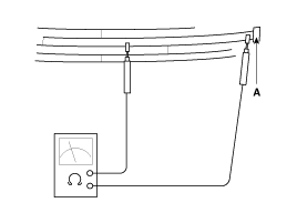
|
- Lightly rub the area around the broken part (A) with fine steel wool, then clean it with alcohol.
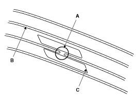
- Carefully tape above and below the broken part of the glass antenna wire (B) with cellophane tape (C).
- Using a small brush, apply a thick layer of silver conductive paint (A) extending approximately 1/8 inch on both sides of the break. Allow 30 minutes to dry.
Stir the paint thoroughly before use.
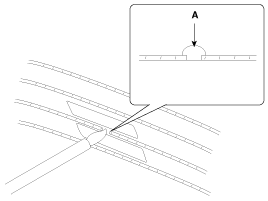
- Check the continuity of the repaired wire.
- In the same way, apply a second layer of paint. Allow it to dry for three hours before removing the tape.
- Remove the right rear quarter trim panel. Then disconnect the antenna feeder cable (A) from the glass antenna amplifier.
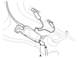
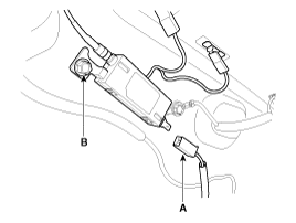
- Turn on the radio. Measure the voltage between the power cable at the wiring harness side (A) and the body ground (B).
OK: Approximately 12 V (ACC+)
- Check the FM wire resistance between terminals No. 1 and No. 3. 1. FM antenna grid terminal 2. AM antenna grid terminal 3. Body ground.
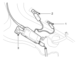
Standard value: 80~120 kΩ; Short: approx. 0 Ω; Open: ∞
- Check the resistance of the AM wire between terminals No. 2 and No. 3.
Standard value: 120~170 kΩ; Short: approx. 0 Ω; Open: ∞
- Check the grid lines for continuity.
- If poor radio reception is not resolved by the above checks, replace the amplifier. If radio reception is still poor, check the radio cable for a short circuit and the head unit for malfunction.
- Disconnect the antenna connector (A) from the audio unit and antenna.
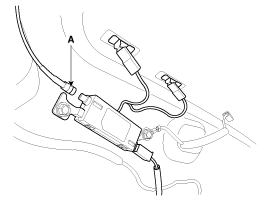
- Check continuity between the center terminals of the antenna cable.
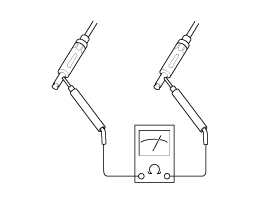
- Check continuity between the outer terminals of the antenna cable. There should be continuity.
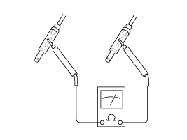
- If there is no continuity, replace the antenna cable.
- Check continuity between the center terminal (A) and the outer terminal (B) of the antenna cable. There should be no continuity.
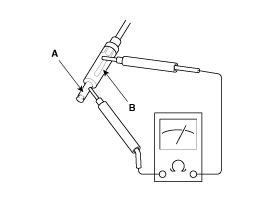
- If there is continuity, replace the antenna cable.
Removal
- Disconnect the negative (-) battery terminal.
- Remove the rear roof trim. (Refer to Body - "Roof Trim")
- Disconnect the connector (A) from the roof antenna.
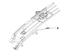
- Remove the roof antenna (A) by unscrewing the nut.
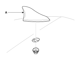
Installation
- Install the roof antenna.
- Connect the connector.
- Install the rear roof garnish.
- Connect the battery negative (-) terminal.
Test yourself
A quick Kia Optima Hybrid Owner's Manual quiz: every answer comes with an explanation and a link to the manual page.
Was this page helpful?