Automatic Transmission
Oil Pump Unit (OPU) Schematic Diagrams
In this manual: Automatic Transmission
~3min read
OPU Connector and Terminal Function
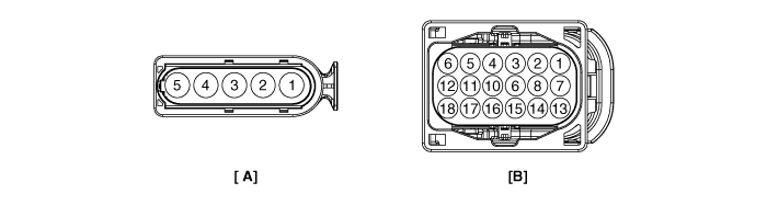
OPU Terminal Function
[A]| Pin | Description |
| 1 | Main Relay Power |
| 2 | Ground |
| 3 | Motor Phase Power (U) |
| 4 | Motor Phase Power (V) |
| 5 | Motor Phase Power (W) |
[B]
| Pin | Description |
| 1 | Battery Power (+) |
| 2 | Battery Power (+) |
| 3 | CAN Communication Line (Low) |
| 4 | OPU Status Signal |
| 5 | Hall Sensor Ground |
| 6 | Hall Sensor Power (+5V) |
| 7 | IG_Key |
| 9 | CAN Communication Line (HIGH) |
| 11 | Hall Signal A |
| 12 | Main Relay Operation Signal |
| 13 | Ground |
| 14 | Ground |
| 15 | Motor Speed Control Signal |
| 17 | Hall Signal B |
| 18 | Hall Signal C |
OPU Terminal Input/Output Signal
[A]| Pin | Description | Condition | Input/Output Value | |
| Type | Level | |||
| 1 | Main Relay Power | Ignition OFF ------------------ After start (OFF) ------------------ After start (ON) |
DC Voltage | - -------------------- Max. 0.5 V -------------------------- Battery voltage |
| 2 | Ground | Ignition OFF ------------------ Ignition ON |
DC Voltage | - -------------------- Max. 0.5 V |
| 3 | Motor Phase Power (U) | Ignition OFF ------------------ After start (OFF) ------------------ After start (ON) |
PWM | - -------------------- Max. 0.5 V -------------------------- Battery voltage |
| 4 | Motor Phase Power (V) | Ignition OFF ------------------ After start (OFF) ------------------ After start (ON) |
PWM | - -------------------- Max. 0.5 V -------------------------- Battery voltage |
| 5 | Motor Phase Power (W) | Ignition OFF ------------------ After start (OFF) ------------------ After start (ON) |
PWM | - -------------------- Max. 0.5 V -------------------------- Battery voltage |
[B]
| Pin | Description | Condition | Input/Output Value | |
| Type | Level | |||
| 1 | Battery Power (+) | Ignition OFF ------------------ After start ------------------ Start OFF (dark current) |
DC Voltage | Battery voltage -------------------- Battery voltage -------------------- Max. 5 mA |
| 2 | Battery Power (+) | Ignition OFF ------------------ After start ------------------ Start OFF (dark current) |
DC Voltage | Battery voltage -------------------- Battery voltage -------------------- Max. 5 mA |
| 3 | CAN Low | Ignition OFF ------------------ Recessive ------------------ Dominant |
Pulse | - -------------------- 2.0 ~ 3.0 V -------------------- 0.5 ~ 2.25 V |
| 4 | OPU Status Signal | Ignition OFF ------------------ After start (low) ------------------ After start (high) |
Pulse | - -------------------- Max. 1.0 V -------------------------- 0 V / Battery voltage level 9 V < Battery voltage level < 16 V |
| 5 | Hall Sensor Ground | Ignition OFF ------------------ Ignition ON |
DC Voltage | - -------------------- Max. 0.5 V |
| 6 | Hall Sensor Power (+5V) | Ignition OFF ------------------ Ignition ON |
DC Voltage | - -------------------- 5.0 V ± 0.5 V |
| 7 | IG_Key | Ignition OFF ------------------ Ignition ON |
DC Voltage | - -------------------- Battery voltage |
| 9 | CAN High | Ignition OFF ------------------ Recessive ------------------ Dominant |
Pulse | - -------------------- 2.0 ~ 3.0 V -------------------- 2.75 ~ 4.5 V |
| 11 | Hall Signal A | Ignition OFF ------------------ After start (low) ------------------ After start (high) |
Pulse | - -------------------- Max. 0.5 V -------------------------- 5.0 V ± 0.5 V |
| 12 | Main Relay Operation Signal |
Ignition OFF ------------------ After start (OFF) ------------------ After start (ON) |
DC Voltage | - -------------------- Battery voltage level -------------------------- Battery voltage level |
| 13 | Ground | Ignition OFF ------------------ Ignition ON |
DC Voltage | - -------------------- Max. 0.5 V |
| 14 | Ground | Ignition OFF ------------------ Ignition ON |
DC Voltage | - -------------------- Max. 0.5 V |
| 15 | Motor Speed Command Signal |
Ignition OFF ------------------ After start (low) ------------------ After start (high) |
Pulse | - -------------------- Max. 0.5 V -------------------------- 0 V / Battery voltage level 9 V < Battery voltage level < 16 V |
| 17 | Hall Signal B | Ignition OFF ------------------ After start (low) ------------------ After start (high) |
Pulse | - -------------------- Max. 0.5 V -------------------------- 5.0 V ± 0.5 V |
| 18 | Hall Signal C | Ignition OFF After start (low) ------------------ After start (high) |
Pulse | - -------------------- Max. 0.5 V -------------------------- 5.0 V ± 0.5 V |
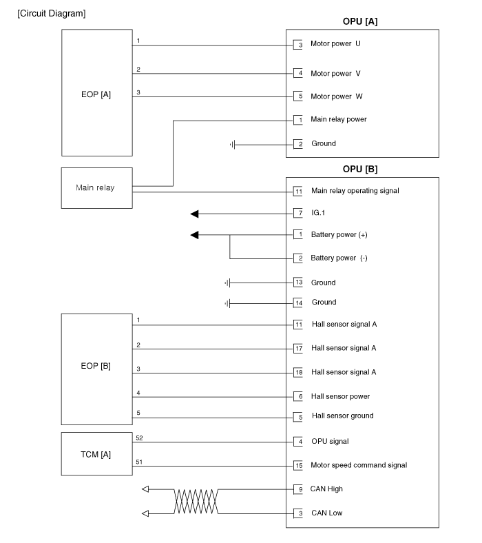
Wiring Diagram
Test yourself
A quick Kia Optima Hybrid Owner's Manual quiz: every answer comes with an explanation and a link to the manual page.
Was this page helpful?