Crankshaft
Components and Component Location
Components
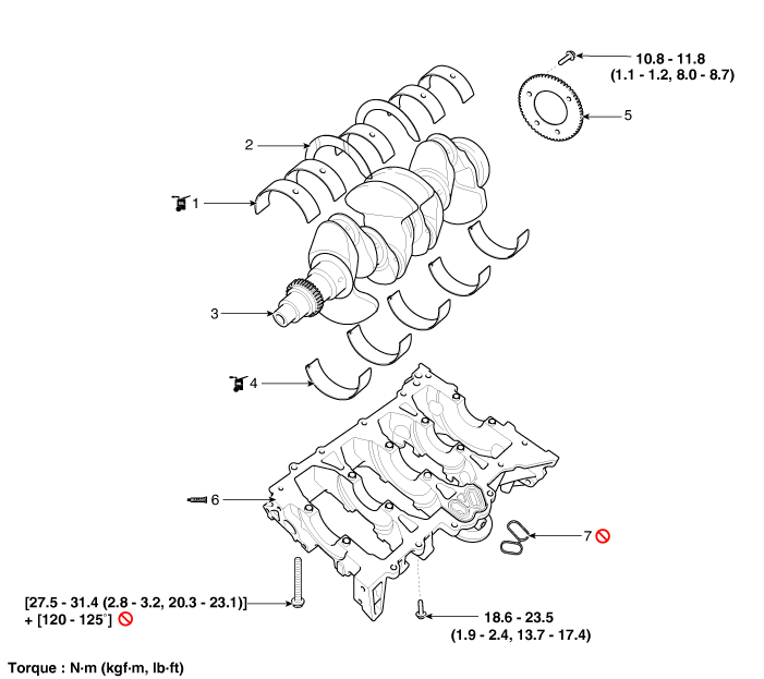
| 1. Crankshaft upper bearing 2. Crankshaft thrust bearing 3. Crankshaft 4. Crankshaft lower bearing |
5. Crankshaft Position Sensor (CKPS) wheel 6. Lower block 7. Gasket |
Repair Procedures
Disassembly
Remove the engine assembly from the vehicle.
(See Engine and Transaxle Assembly - "Engine and Transaxle Assembly")
Remove the transaxle assembly from the engine assembly.
(Refer to Automatic Transmission System - Automatic Transmission)
Remove the drive plate.
(Refer to Cylinder Block - Drive Plate)
Remove the rear oil seal.
(See Cylinder Block - "Rear Oil Seal")
Install the engine on an engine stand for disassembly.
Remove the timing chain.
(See Timing System - Timing Chain)
Remove the water pump assembly.
(See Cooling System - "Water Pump")
Remove the water inlet pipe and thermostat assembly.
(See Cooling System - "Thermostat")
Remove the intake manifold.
(See Intake and Exhaust System - Intake Manifold)
Remove the air conditioning compressor.
(See Heating, Ventilation and Air Conditioning - "Compressor")
Remove the exhaust manifold.
(See Intake and Exhaust System - Exhaust Manifold)
Remove the cylinder head assembly.
(See Cylinder Head Assembly - Cylinder Head)
Remove the oil filter.
(See Lubrication System - Engine Oil)
Remove the oil screen.
(See Lubrication System - Oil Pan)
Remove the piston and connecting rod assembly.
(Refer to Cylinder Block - Piston and Connecting Rod)
Check the crankshaft bearing oil clearance.
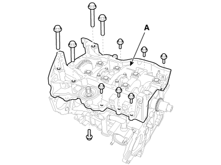
Remove the lower oil pan (A).
Remove the lower oil pan bolts.
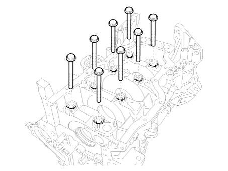
Remove the main bearing cap bolts.
Check the crankshaft end play.
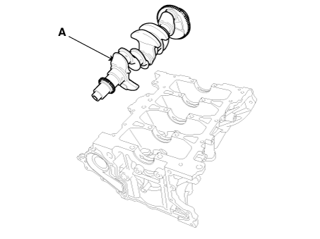
Lift the crankshaft (A) out of the engine, taking care not to damage the journals.
Inspection
Check the crankshaft bearing oil clearance.
To check the oil clearance between the main bearing and journal, remove the lower crankcase and lower bearings.
Clean each main journal and bearing with a clean shop towel.
Place one strip of Plastigage on each main journal.
Install the lower block and lower bearings, then tighten the main bolts.
Tightening Torque
Step 1:
27.5–31.4 N·m (2.8–3.2 kgf·m, 20.3–23.1 ft-lbf)
Step 2: 120–125°
Remove the lower crankcase and lower bearings.
Measure the width of the Plastigage at its widest point.
Oil clearance: 0.016–0.034 mm (0.00063–0.00134 in.)
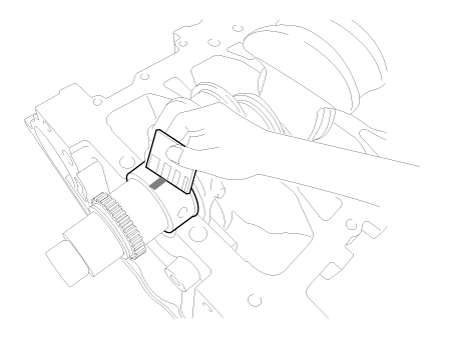
If the Plastigage is too wide or too narrow, remove the upper and lower bearings, then install new bearings with the same color code. Re-check the oil clearance.
If the Plastigage indicates that the clearance is still incorrect, try the next larger or smaller bearing. Recheck the oil clearance.
Crankshaft main journal bore identification mark
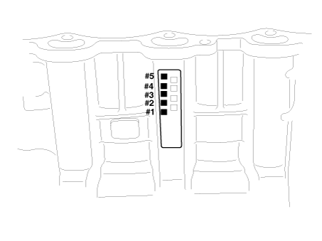
Letters are stamped on the block to indicate the size of each of the 5 main bearing bores.
Use these letters, along with the numbers or marks stamped on the crankshaft (main journal size marks), to select the correct bearings.
Cylinder Block Specifications
Grade Mark Inner Diameter a A 59.000 - 59.006 mm
(2.32283 - 2.32307 in.)D B 59.006 - 59.012 mm
(2.32307 - 2.32330 in.)c C 59.012 - 59.018 mm
(2.32330 - 2.32354 in.)
Crankshaft journal identification mark
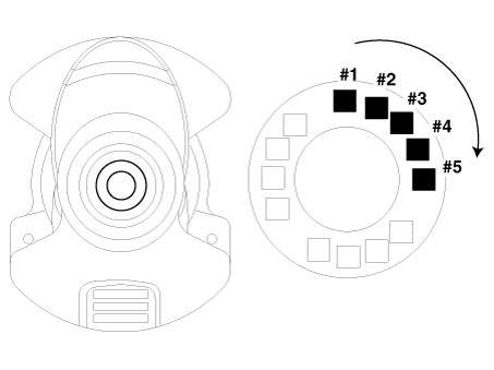
Crankshaft Specifications
Grade Mark Journal Outside Diameter I 1 54.954 - 54.960 mm
(2.16354 - 2.16378 in.)II 2 54.948 - 54.954 mm
(2.16330 - 2.16354 in.)III 3 54.942 - 54.948 mm
(2.16307 - 2.16330 in.)
Crankshaft bearing marking
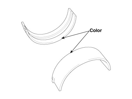
Crankshaft bearing specifications
Grade Mark Bearing Thickness A Blue 2.021 - 2.024 mm
(0.07957–0.07968 in.)B Black 2.018 - 2.021 mm
(0.07945–0.07957 in.)C None 2.015 - 2.018 mm
(0.07933–0.07945 in.)D Green 2.012 - 2.015 mm
(0.07921–0.07933 in.)E Yellow 2.009 - 2.012 mm
(0.07909–0.07921 in.)Select the crankshaft bearing using the selection table.
Crankshaft Bearing Selection Table
Bearing Classification Assembly Crankshaft Bore Identification Mark A (A) B (B) C (C) Crankshaft Marking I (1) E (Yellow) D (Green) C (None) II (2) D (Green) C (None) B (Black) III (3) C (None) B (Black) Blue)
Check the crankshaft end play.
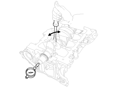
Using a dial indicator, measure the crankshaft thrust clearance by prying the crankshaft forward and rearward with a screwdriver.
If the thrust clearance exceeds the maximum, replace the center bearing.
End of play. Standard: 0.07–0.25 mm (0.0028–0.0098 in.)
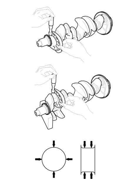
Inspect the main journals and crankpins.
Using a micrometer, measure the diameter of each main journal and crankpin.
Main journal diameter:
54.942–54.960 mm (2.16307–2.16378 in)
Crankpin diameter:
44.954–44.972 mm (1.76984–1.77055 in)
Installation
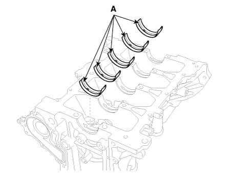
Install the crankshaft main bearings.
Align the protrusion of the bearing with the groove in the cylinder block, and install the 5 upper bearings (A).
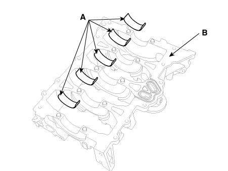
Align the bearing tab with the groove in the lower block. (B) and install the 5 lower bearings (A).
Install the thrust bearings.
Install the 2 thrust bearings (A) on both sides of the No. 3 journal of the cylinder block with the oil groove facing outward.
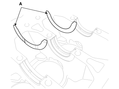
Install the crankshaft (A) on the cylinder block.
Apply liquid sealant to the upper surface of the lower crankcase.
Using a gasket scraper, remove all old gasket material from the sealing surfaces.
There must be no foreign material, oil, dust, or moisture on the sealant application areas of the lower block and the cylinder block. Spray cleaning agent onto the surface and wipe with a clean rag.
Install a new rubber gasket (A) on the upper part of the lower crankcase.
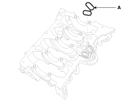
Apply liquid sealant to the lower part of the cylinder block. Apply a continuous bead of sealant to prevent any oil leakage.
Bead width: 2.5–3.5 mm (0.10–0.14 in.)
Sealant: Threebond 1217H or equivalent.
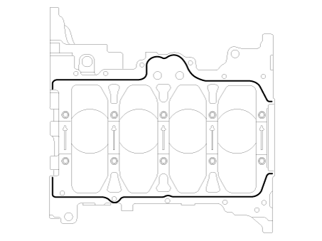
Install the lower crankcase on the cylinder block.
Install the main bearing cap bolts.
Using SST (09221-4A000), install and tighten the 10 main bearing cap bolts in several passes in the sequence shown.
Tightening Torque
Step 1:
27.5–31.4 N·m (2.8–3.2 kgf·m, 20.3–23.1 ft-lbf)
Step 2: 120–125°
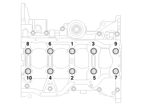
Install the lower block bolts and tighten them in several passes in the sequence shown.
Tightening torque: 18.6–23.5 N·m (1.9–2.4 kgf·m, 13.7–17.4 ft-lbf)
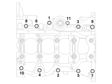
Make sure the crankshaft rotates smoothly.
Check the crankshaft end play.
Assemble the remaining components in the reverse order of removal.
Test yourself
A quick Kia Optima DL3 quiz: every answer comes with an explanation and a link to the manual page.