Heater
Components and Component Location
Component Location
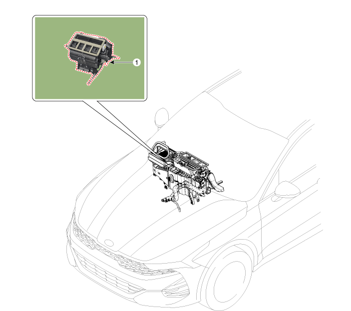
| 1. Heater Unit Assembly |
Components
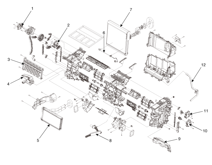
| 1. Mode Control Actuator 2. Temperature Control Actuator [LH] 3. PTC Heater Assembly 4. Vent Duct [LH] 5. Heater Core Assembly 6. Evaporator Temperature Sensor |
7. Evaporator Core 8. Intake Hose 9. Vent Duct [RH] 10. Temperature Control Actuator [RH] 11. Defog Actuator 12. Drain Hose |
Repair Procedures
Replacement
Disconnect the negative (-) battery terminal.
Recover the refrigerant using a recovery/recycling/charging station.
When the engine has cooled, drain the engine coolant from the radiator.
G 2.0 NU MPI (Refer to Engine Mechanical System - "Engine Coolant")
G 2.5 GDI THETA II (Refer to Engine Mechanical System - "Engine Coolant")
Remove the upper hood cover.
(Refer to Body - "Upper Cowl Cover")
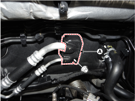
Loosen the nut and remove the expansion valve cover (A).
Tightening torque: 8.8–13.7 N·m
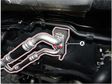
Loosen the mounting bolts and separate the expansion valve (A) from the evaporator core.
Tightening torque: 8.8–13.7 N·m
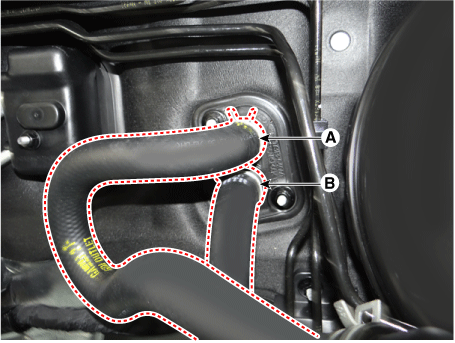
Disconnect the heater hoses (A) and (B).
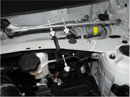
Loosen the hood cross member mounting bolts.
Remove the front seat assembly.
(Refer to Body - "Front Seat Assembly")
Remove the floor console assembly.
(Refer to Body - Floor Console Assembly)
Remove the air bag center panel.
(Refer to Body - "Center Crash Pad Panel")
Remove the front pillar trim.
(See Body - Front Pillar Garnish)
Remove the hood side trim.
(See Body - Hood Side Garnish)
Remove the steering column lower cover panel.
(Refer to Body - "Steering Column Shroud Panel")
Remove the steering wheel.
(Refer to Steering System - "Steering Wheel")
Remove the multifunction switch.
(Refer to Body Electrical System - "Multifunction Switch")
Lower the steering column after loosening the mounting bolts.
(Refer to Steering System - "Steering Column and Shaft")
Remove the accelerator pedal.
(Refer to Engine Controls / Fuel System - "Accelerator Pedal")
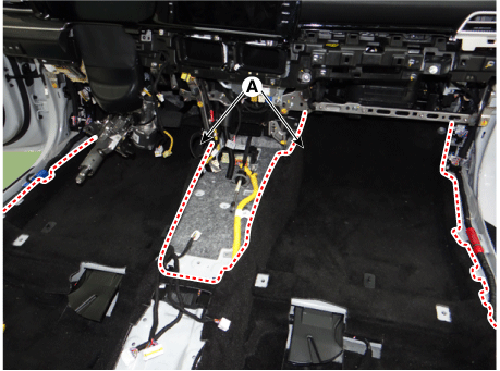
Remove the floor carpet (A) to gain access for removing the rear compartment heater duct.
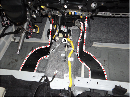
Remove the rear heater duct (A).
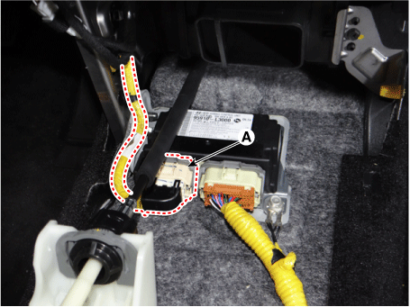
Disconnect the connector (A) of the SRS control module (SRSCM).
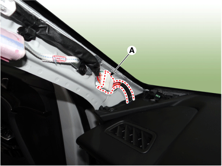
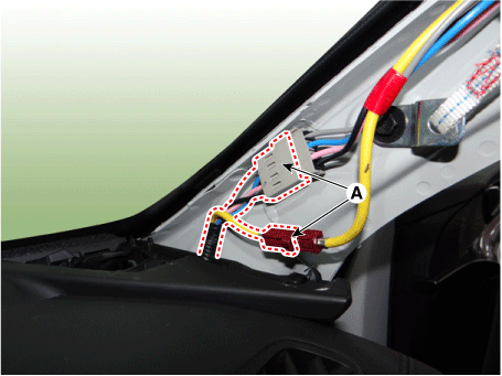
Loosen the front pillar mounting clips and disconnect the connectors (A).
[LH]
[RH]
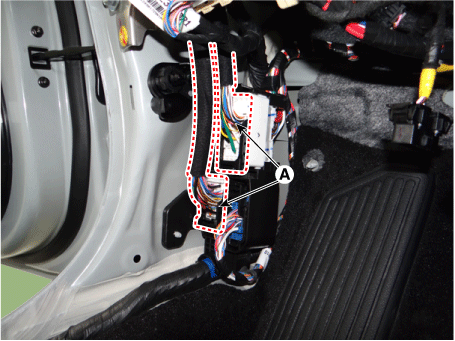
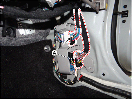
Disconnect the junction block connectors (A).
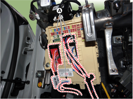
Disconnect the multi-box connectors (A).
[LH]
[RH]
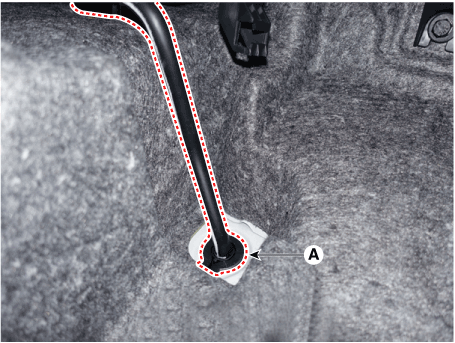
Remove the drain hose (A).
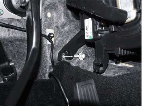
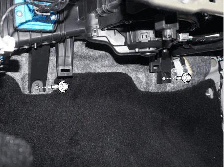
Remove the lower mounting bolt of the blower unit.
Tightening torque: 3.9 ~ 5.9 N·m
[LH]
[RH]
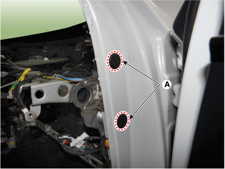
Remove the plug hole covers (A).
Loosen the side mounting bolts of the hood cross member.
[LH]
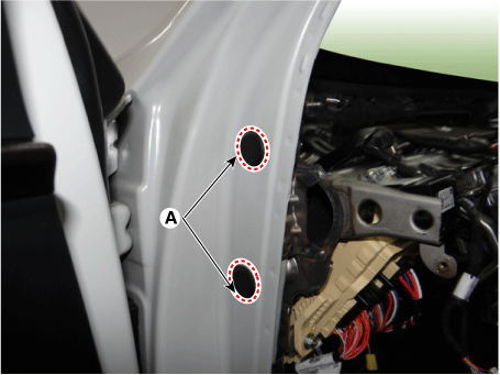
[RH]
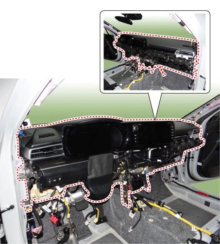
After loosening the bolts and nuts, remove the protector and the heater and blower unit assembly (A) together.
Remove the Integrated Body Control Unit.
(Refer to Body Electrical System - "Integrated Body Control Unit (IBU)").
Remove the heater control unit.
(Refer to Heating, Ventilation and Air Conditioning - Heater Control Unit)
Disconnect the connectors and wiring of the heater unit and blower.
[LH]
Disconnect the temperature control actuator [LH] (A) and mode control actuator connectors (B).
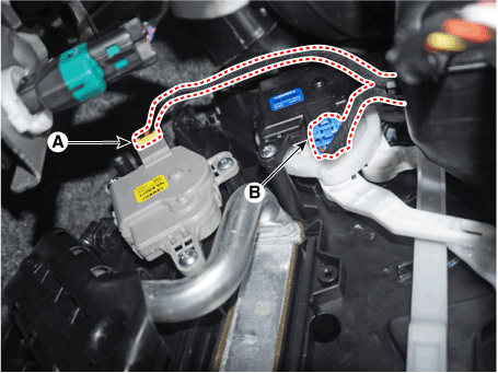
[RH]
Disconnect the connector of the automatic defogging system actuator (A).
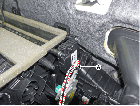
Disconnect the intake actuator (A), cluster ionizer (B), and temperature sensor connectors. Disconnect the [RH] temperature control actuator connector (C).
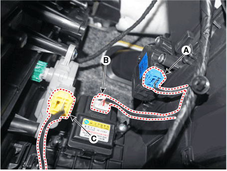
Disconnect the evaporator sensor (A) and power FET (B) connectors.
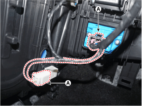
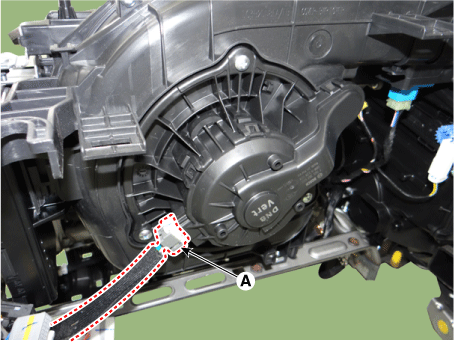
Disconnect the blower motor connector (A).
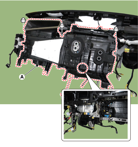
Loosen the mounting nuts and bolts, then remove the heater and blower unit (A) from the emergency pad.
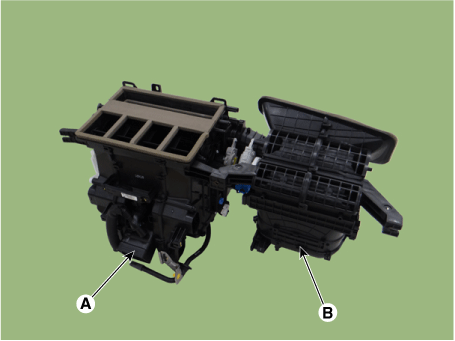
Loosen the mounting screws, then separate the heater unit (A) and the blower unit (B).
To install, reverse the removal procedure.
Test yourself
A quick Kia Optima DL3 quiz: every answer comes with an explanation and a link to the manual page.