Steering
Motor Driven Power Steering
In this manual: Steering
4steps
~24min
2/5difficulty
Done 0 of 4
Description and Operation
Description
The MDPS (Motor Driven Power Steering) system uses an electric motor to assist steering effort, and steering operates independently of engine operation. The MDPS ECU controls motor operation according to information received from each sensor and the CAN (Controller Area Network). This results in more precise and timely control of the steering assist than conventional engine-driven hydraulic systems. The MDPS components (angle sensor, torque sensor, fail-safe relay, etc.) are located inside the steering column. The MDPS assembly, steering column, and MDPS unit must not be disassembled for inspection. Replace them if necessary.Components and Component Location
Components
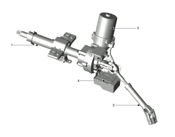
| 1. Steering column 2. Universal joint |
3. MDPS motor 4. MDPS ECU |
Circuit Diagrams
Schematic Diagrams
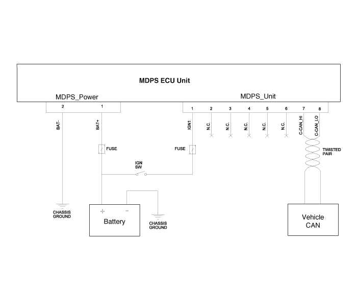
Harness Connector
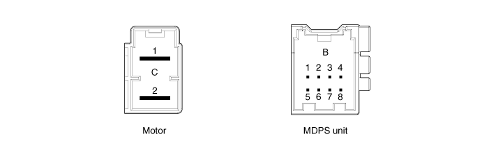
| Type | Pin No. | Description |
| Battery | 1 | Battery + |
| 2 | Battery - | |
| VSS | 1 | IGN |
| 2 | - | |
| 3 | - | |
| 4 | - | |
| 5 | - | |
| 6 | - | |
| 7 | HIGH CAN | |
| 8 | LOW CAN |
Repair Procedures
Airbag System Repair Procedures
MDPS A/S Work Flow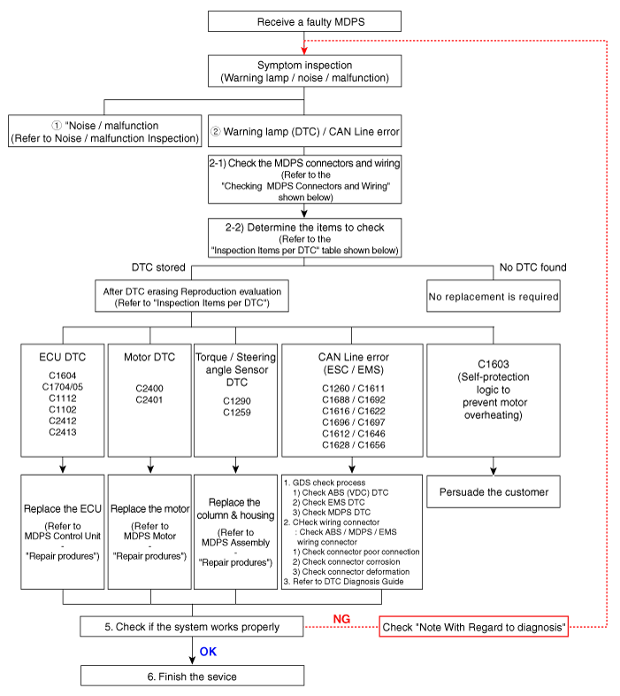
① Connector and Wiring Inspection
- Connector and Wiring Inspection. Check each connector and wiring for damage, binding, or improper connection.
- Check the wiring on the vehicle side.
- Check for open/short circuit due to improper connection, damage, or foreign material.
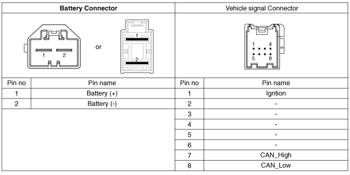
- Check for open/short circuit due to improper connection, damage, or foreign material.
- Check the wiring on the ECU side (motor 3-phase power).
- Check for open/short circuit due to improper connection, damage, or foreign material.

- Check for open/short circuit due to improper connection, damage, or foreign material.
- Check the motor connector.
- Terminal expansion and damage.
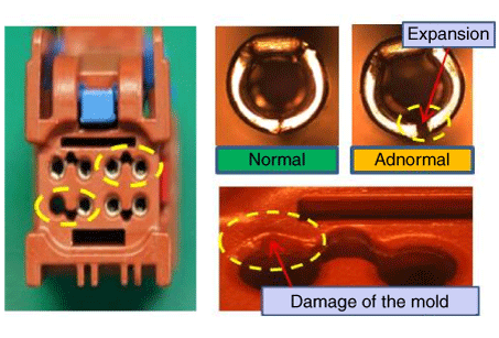
- Terminal expansion and damage.
- Check the motor wiring.
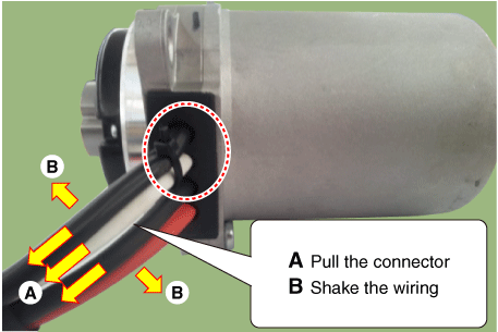
- Check the wiring on the vehicle side.
② DTC Troubleshooting Items
| Item | Trouble Code | Description | Inspection | Service Action |
| CAN line | C1611 | MAY EXCLUDE EMC | 1. Check GDS. 2. Check connector tightening. 3. Inspect the ECU CAN connector. 4. Check the MDPS vehicle ground condition. |
Check the EMS CAN line |
| C1616 | CAN BUS OFF | Check whether the chassis line | ||
| C1622 | Vehicle speed signal error | Check EMS (Engine Control Module) | ||
| Torque Sensor | C1290 | Torque sensor signal error | Check after DTC clear. Check connector tightening. |
Replace the column and housing if the symptom persists |
| C1112 | Torque sensor power supply voltage error | Check the torque sensor and ECU connector. | Replace the ECU if the problem persists | |
| ECU | C1604 | ECU hardware error | Inspect the ECU connector after clearing the DTC. | Replace the ECU if the problem persists |
| ECU | C1705 | EPS module precharge circuit malfunction |
Inspect the ECU connector after clearing the DTC. | Replace the ECU if the problem persists |
| Motor | C2400 | Motor signal error | Check the motor connector after clearing the DTC. | Replace the motor if the problem persists |
| Motor | C2401 | Motor position sensor error | Check the motor connector after clearing the DTC. | Replace the motor if the problem persists |
| ECU / motor | C2412 | Motor current error | Check the motor/ECU connector after clearing the DTC. | Replace the ECU first. Replace the motor if the problem persists |
| Steering Wheel Angle Sensor | C1259 | Steering Wheel Angle Sensor Malfunction | Steering wheel angle reset after DTC clear Check connector tightening. |
Replace the column and housing if the symptom persists |
| Battery | C1102 | Low Battery Voltage | Check the battery voltage condition | Battery charging voltage |
| Coordinated control | C1696 | SPAS signal error | SPAS Inspection | Clear the diagnostic trouble code. |
| C1697 | ||||
| Coordinated control | C1612 | TCU signal error | GTS Inspection | Clear the diagnostic trouble code. |
| C1646 | ||||
| Coordinated control | C1628 | Cluster signal error | Cluster Inspection | Clear the diagnostic trouble code. |
| C1656 | ||||
| Coordinated control | C1692 | VSM signal error | VSM Inspection | Clear the diagnostic trouble code. |
| C1693 | ||||
| ABS | C1260 | Steering Wheel Angle Signal Error | Check after steering wheel angle reset If code C1259 does not appear, check the CAN line. |
Angle reset Clear the trouble code. |
Noise/Malfunction Repair Procedures
③ Noise/Malfunction Inspection
| Symptom | Malfunction Description and Inspection Method | Countermeasure |
| Noise/Rattle | 1. Noise generated near the MDPS column and housing.
|
|
| Noise/Rattle | 1. Check the steering wheel and surrounding fasteners.
|
Check the noise of the corresponding part
|
2. Check where the C-MDPS is installed.
|
Check cover installation | |
3. Check the universal joint bolt mounting area.
|
Secure with a new bolt if the universal joint bolt is worn | |
4. Check steering column free play while steering with the vehicle stationary.
|
Maintain clearance between surrounding parts
|
④ Service Precautions
Precautions when handling MDPS (Motor Driven Power Steering)- Malfunction caused by internal damage from dropping and impact, and excessive external force on the new partial component. → Be careful not to strike the partial component, and replace any damaged part (due to dropping, etc.) with a new one.
- When installing the steering wheel, excessive impact may twist the center point of the torque sensor.
- When removing/installing the connector, wiring may be damaged (deformed) by excessive external force.
- Be careful when storing and replacing individual components under abnormal temperature and humidity conditions.
Test yourself
A quick Kia Picanto JA quiz: every answer comes with an explanation and a link to the manual page.
Was this page helpful?