Pcm inspection
- PIDs for the following parts are not available on this model. Go to the appropriate part inspection page.
- CMP sensor (See CAMSHAFT POSITION (CMP) SENSOR INSPECTION.) - Main relay (See RELAY INSPECTION.)1. Connect the SST
(WDS or equivalent) to the DLC-2.
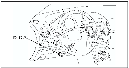
2. Turn the ignition switch to ON position.
3. Measure the PID value.
- If PID value is not within the specification, follow the instructions in Action column.
- The PID/DATA MONITOR function monitors the calculated value of the input/output signals in the PCM. Therefore, an output device malfunction is not directly indicated as a malfunction of the monitored value for the output device. If a monitored value of an output device is out of specification, inspect the monitored value of the input device related to the output control.
- For input/output signals except those of the monitoring items, use a voltmeter to measure the PCM terminal voltage.
- The simulation items that are used in the ENGINE CONTROL SYSTEM OPERATION INSPECTION are as follows.
- ACCS
- ALTF
- EVAPCP
- FAN1
- FAN2
- FAN3
- FP
- HTR11
- HTR12
- IAC
- IASV
- IMRC
- IMTV
- VT DUTY1
PID/DATA monitor table (reference)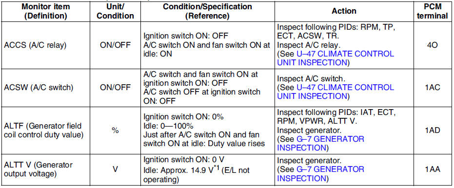
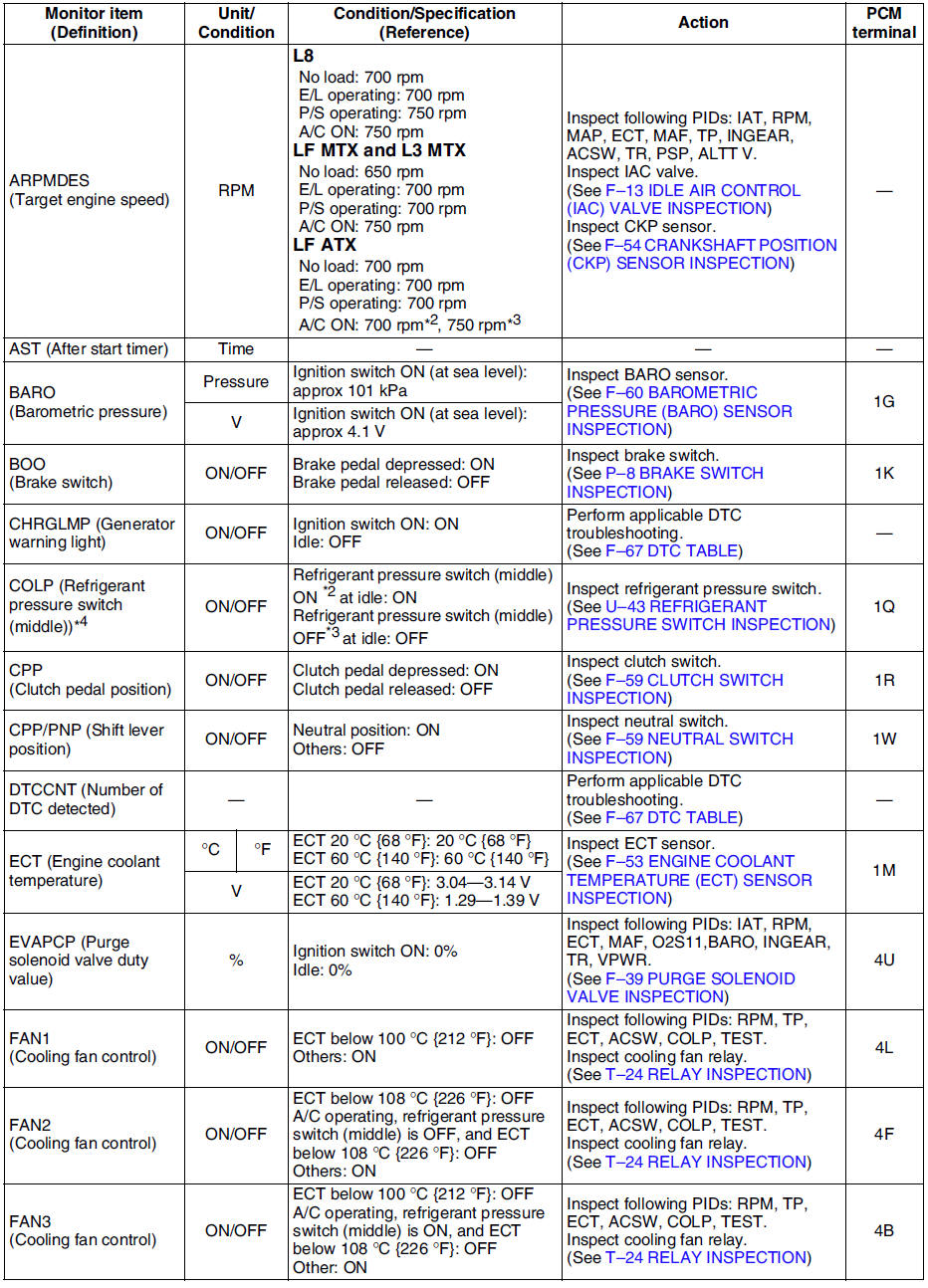
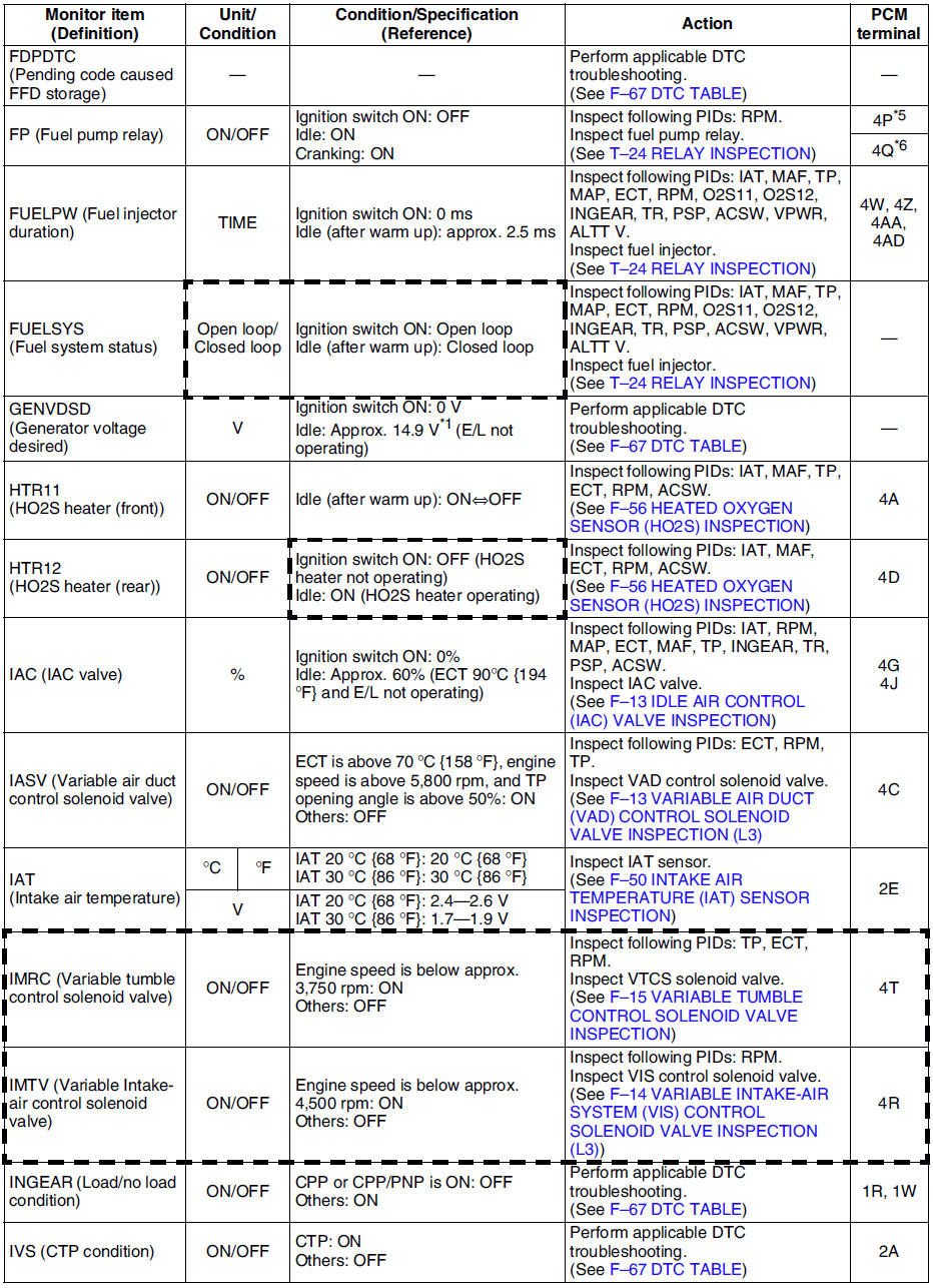
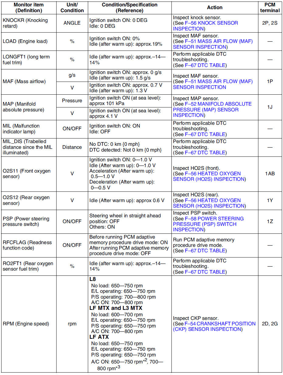
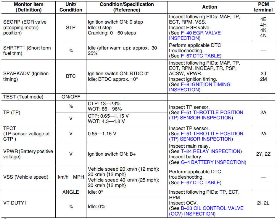
*1 : Calculated value; differs from terminal voltage
*2 : Refrigerant pressure switch (middle) turns on when the refrigerant pressure is 1.691.84 MPa {17.318.7 kgf/cm2, 247265 psi}
*3 : Refrigerant pressure switch (middle) turns off when the refrigerant pressure is 1.261.49 MPa {12.915.1 kgf/cm2, 184214 psi}
*4 : L3 and L8, LF (Intensely hot area) models
*5 : Immobilizer system equipped
*6 : Immobilizer system not equipped
- Following PIDs are for the ATX models. If inspects for following PIDs, see PID/DATA MONITOR INSPECTION.
PIDs for the ATX models
- GEAR
- LINEDES
- LPS
- OP_SW_B
- SSA/SS1
- SSB/SS2
- SSC/SS3
- TCS
- TFT
- TFTV
- THOP
- TR
- TR_SENS
- TSS
Test yourself
A quick Mazda 6 quiz: every answer comes with an explanation and a link to the manual page.