Brakes
Brake controls
In this manual: Brakes
17steps
~102min
4/5difficulty
Done 0 of 17
MASTER CYLINDER
 Before loosening hoses and pipes, drain the fluid, then plug all open ports with clean, suitable caps.
REMOVAL
- Disconnect the battery.
- Set the washer fluid reservoir aside without disconnecting the hoses.
- Using a syringe, draw out as much brake fluid as possible from the expansion reservoir.
- Disconnect:
- the brake fluid level sensor connector,
- the clutch slave cylinder supply hose from the brake fluid reservoir.
- Disconnect the hydraulic pipes (1) from the master cylinder after marking them (Fig.21).
- Remove:
- the 2 nuts (arrows) securing the master cylinder,
- the master cylinder (2).
INSTALLATION
Observe the following points:
- replace the master cylinder mounting nuts,
- observe the specified tightening torques,
- replace the seal between the master cylinder and the brake booster,
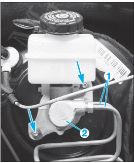
Fig. 21
- bleed the hydraulic brake circuit (see relevant operation).
BRAKE BOOSTER
 Before loosening hoses and pipes, drain the fluid, then plug all open ports with clean, suitable caps.
REMOVAL AND REFITTING
In the engine compartment
- Remove the master cylinder (see relevant operation).
- Disconnect the vacuum hose from the brake booster.
- Disconnect the hydraulic pipes (1) and (2) from the hydraulic unit (3) (Fig.22).
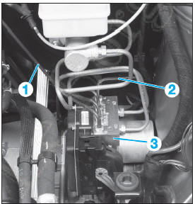
Fig. 22
In the passenger compartment
- Disconnect the brake light switch connector (4) (Fig.23).
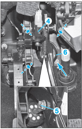
Fig. 23
- Remove the clip (5) from the pin (6) and withdraw the pin.
- Remove the 4 nuts (arrows) securing the brake booster.
- Remove the brake booster through the engine compartment.
To refit, reverse the removal procedure, observing the following points:
- always replace the brake booster seal,
- replace the nuts securing the brake booster,
- make sure the clip (5) is correctly positioned,
- bleed the brake circuit (see relevant operation),
- check:
- the brake fluid level,
- the brake system for leaks,
- the braking system efficiency
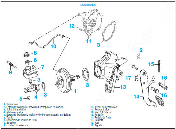
Controls
- Brake booster
- Brake booster mounting nut (replace): 2 daN.m
- Seal
- Master cylinder
- Master cylinder mounting nut (replace): 1.5 daN.m
- Filter screen
- Brake fluid reservoir
- Cap
- Reservoir mounting
- Vacuum hose
- Vacuum pump
- Bolt: 1.2 daN.m
- Pedal box
- Brake pedal
- Spring
- Pin
- Clip.
VACUUM PUMP
REMOVAL AND REFITTING
- Remove:
- the engine undertray,
- the air filter housing,
- the turbocharger (see operation in the 'ENGINE' section),
- the common rail high-pressure rail (see operation in the 'ENGINE' section),
- the injectors (see operation in the 'ENGINE' section).
- Remove the cylinder head cover in the reverse order of the steps shown (Fig.24).
 Cover the openings left open by removing the cylinder head cover with a clean cloth, especially the timing case opening and the injector openings.
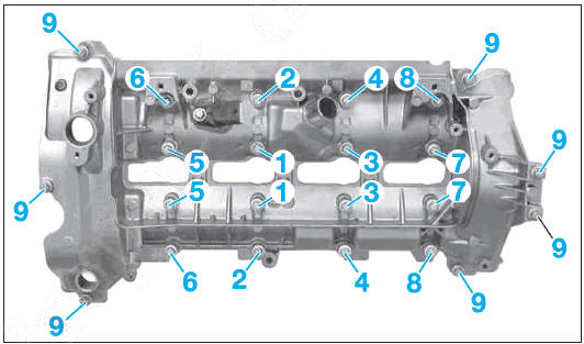
Fig. 24
- Remove the front cover with the vacuum pump (Fig.25):
- remove the bolts (1),
- pull the front cover (3) fitted with the vacuum pump (4) off the locating dowels (2).
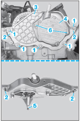
Fig. 25
 The front cover (3) must be removed with care, as the oil pipe (5) may deform and break in the cylinder head.
- Remove the bolts (6) and withdraw the vacuum pump (4) from the front cover (3).
To refit, reverse the removal procedure, observing the following points:
- clean all gasket mating surfaces,
- replace all gaskets,
- align the vacuum pump drive with the exhaust camshaft,
- take care with the locating dowels (2).
Test yourself
A quick Mercedes-Benz B-Class quiz: every answer comes with an explanation and a link to the manual page.
Was this page helpful?